Workpiece clamping mechanism of multi-wire cutting machine

A technology of multi-wire cutting machine and clamping mechanism, which is applied to work accessories, manufacturing tools, stone processing equipment, etc., and can solve problems such as stress concentration, uneven surface of silicon crystal rods, and affecting processing quality

Inactive Publication Date: 2011-09-28
WUXI MACHINETOOL
View PDF9 Cites 4 Cited by
  • Summary
  • Abstract
  • Description
  • Claims
  • Application Information

AI Technical Summary

Problems solved by technology

[0002] The clamping mechanism of the existing equipment is rigid clamping. Due to the uneven surface of the silicon crystal rod, stress concentration will occur after clamping, which will affect the processing quality

Method used


Image

  • Workpiece clamping mechanism of multi-wire cutting machine
  • Workpiece clamping mechanism of multi-wire cutting machine
  • Workpiece clamping mechanism of multi-wire cutting machine

Examples


Embodiment Construction

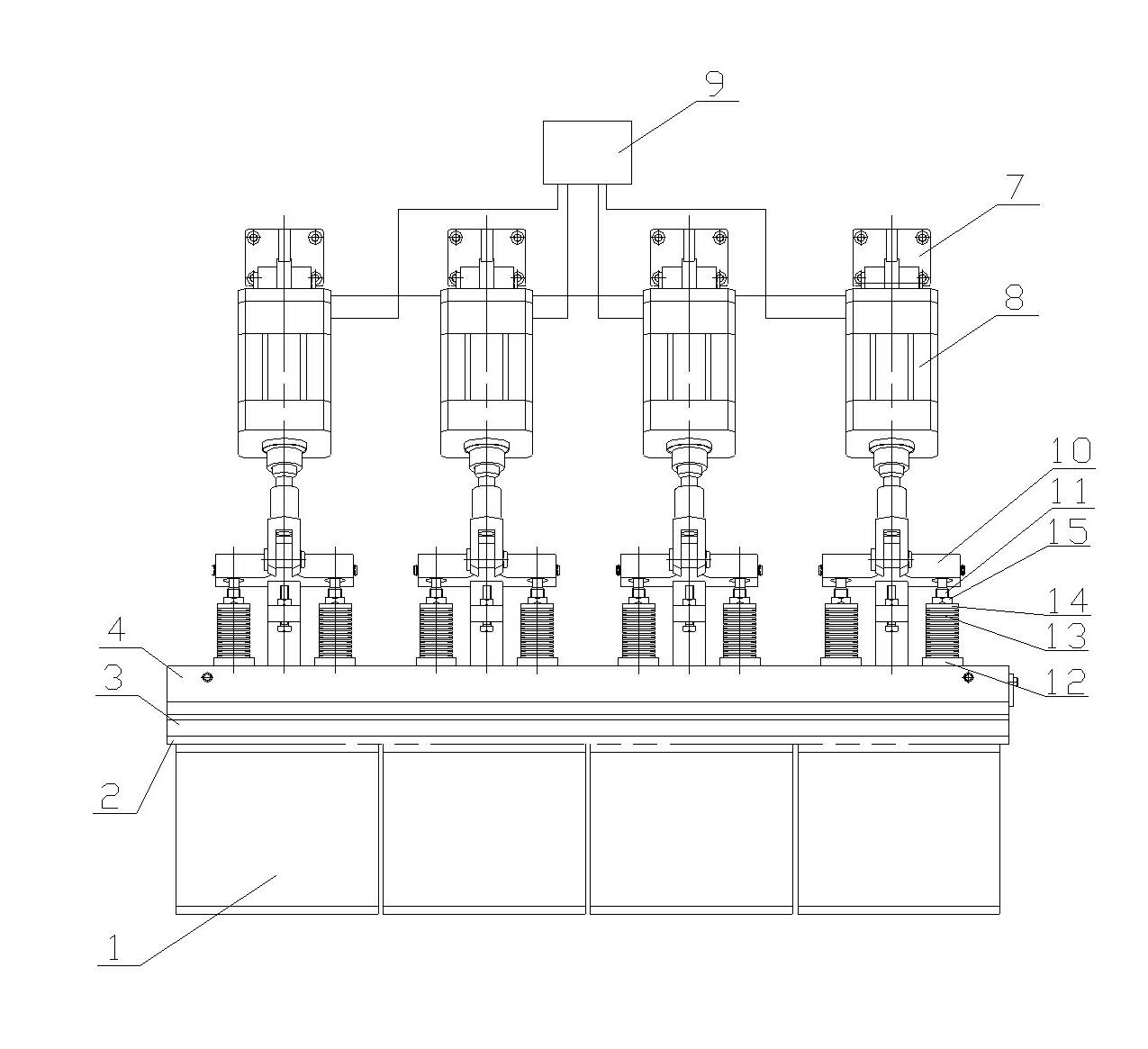
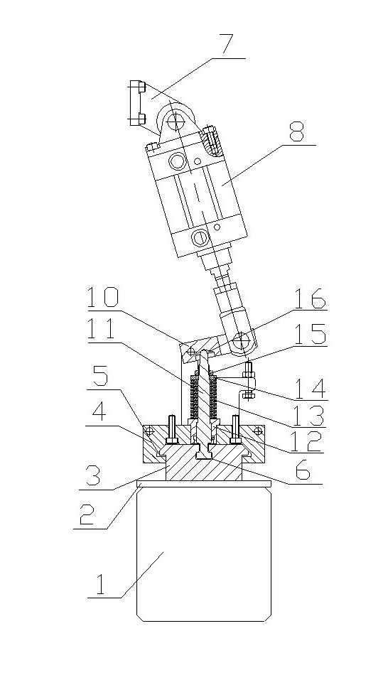
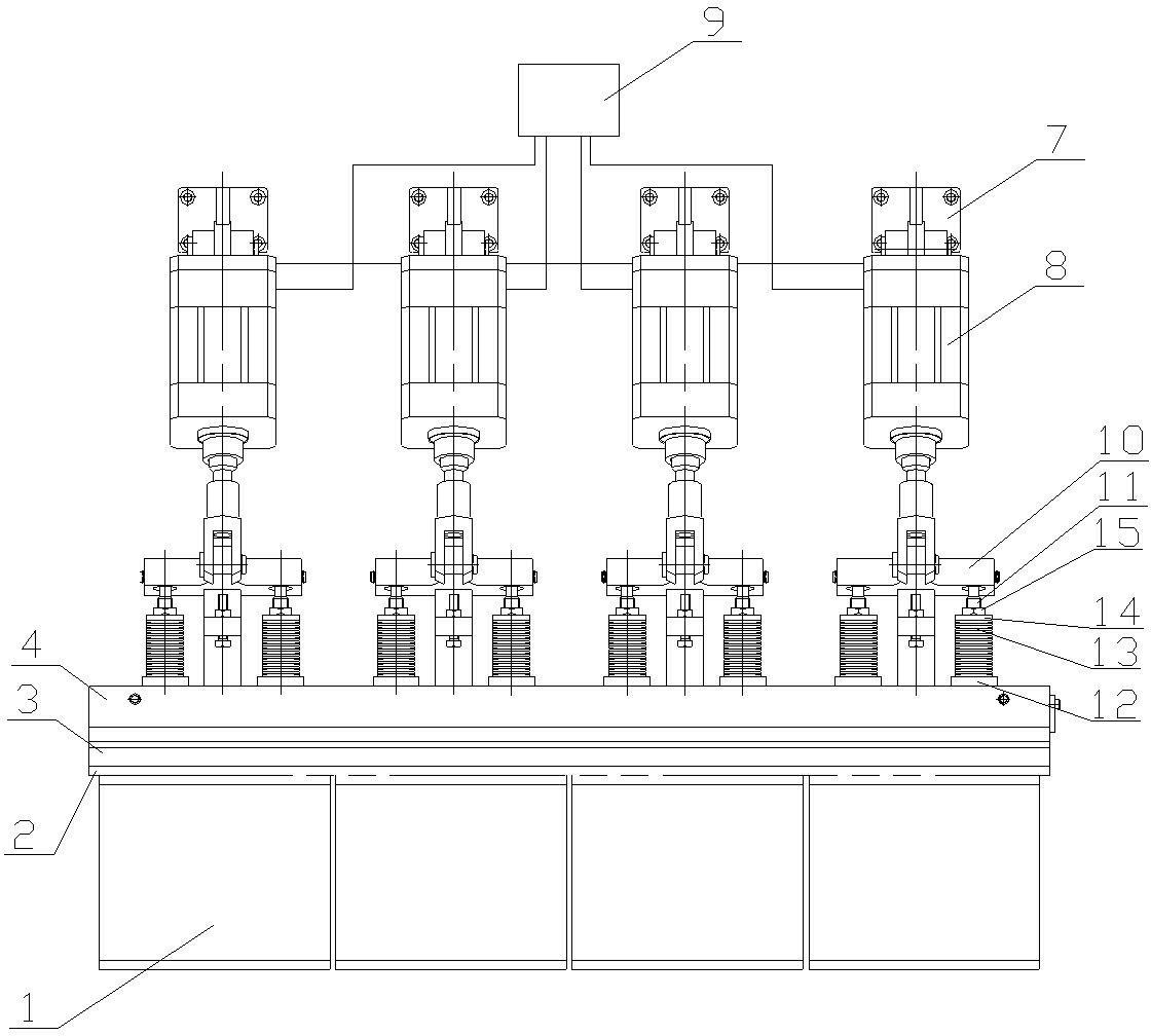
[0009] See figure 1 , figure 2 , the upper surface of the silicon ingot 1 is close to the glass plate 2, the upper surface of the glass plate 2 is fastened to the lower lifting plate 3, and the upper part of the lower lifting plate 3 is inserted into the linear installation groove 5 of the upper lifting plate 4 , the position of the upper lifting plate 4 is fixed, the cross-section of the linear installation groove 5 is trapezoidal and the bottom is open, the center of the upper end face of the lower lifting plate 3 is provided with a large lower and upper small linear groove body 6, and the upper part of the upper lifting plate 4 is Double clevis seats 7 are arranged, the positions of the evenly distributed double clevis seats 7 are fixed, the lower part of each double clevis seat 7 is connected with a cylinder 8, the cylinder 8 is connected with the same pneumatic valve 9, and the top rod of the cylinder 8 is connected with the lower bracket 10, Both sides of the lower bra...


PUM


Abstract

The invention provides a workpiece clamping mechanism of a multi-wire cutting machine. The surface of a clamped silicon crystal bar is stressed uniformly, and the processing quality is good. The workpiece clamping mechanism comprises the silicon crystal bar. The workpiece clamping mechanism is characterized in that: the upper surface of the silicon crystal bar is tightly attached to a glass plate, the upper surface of the glass plate is fastened and connected with a lower lifting plate, the upper part of the lower lifting plate is inserted into a linear installation groove of an upper lifting plate, the position of the upper lifting plate is fixed, the section of the linear installation groove is trapezoidal, the bottom of the linear installation groove is open, the central position of the upper end face of the lower lifting plate is provided with a small end up straight groove body, double-lug ring seats are uniformly distributed above the upper lifting plate, the positions of the uniformly distributed double-lug ring seats are fixed, the lower part of each double-lug ring seat is connected with a cylinder, the cylinders are connected with the same pneumatic valve, ejector rods of the cylinders are connected with a lower bracket, two sides of the lower bracket press the top of a pull rod, and the bottom of the pull rod is arranged in the small end up straight groove body.

Description

technical field [0001] The invention relates to the technical field of the structure of a multi-wire cutting machine, in particular to a workpiece clamping mechanism of the multi-wire cutting machine. Background technique [0002] The clamping mechanism of the existing equipment is rigid clamping. Due to the uneven surface of the silicon ingot, stress concentration will occur after clamping, which affects the processing quality. SUMMARY OF THE INVENTION [0003] In order to solve the above problems, the present invention provides a workpiece clamping mechanism of a multi-wire cutting machine, which has uniform force on the surface of the silicon ingot after clamping and good processing quality. [0004] The technical solution of the workpiece clamping mechanism of the multi-wire cutting machine is as follows: it includes a silicon crystal rod, characterized in that: the upper surface of the silicon crystal rod is in close contact with a glass plate, and the upper surface o...

Claims


Application Information

Patent Timeline
Patent Type & Authority Applications(China)
IPC IPC(8): B28D7/04
Inventor 罗期望
Owner WUXI MACHINETOOL
Why Eureka
Try Eureka