Thin type hoister for elevator and elevator device
A hoist and elevator technology, applied in the hoist field, can solve problems such as increasing the width of the hoist, and achieve the effect of increasing the degree of freedom and reducing the width
- Summary
- Abstract
- Description
- Claims
- Application Information
AI Technical Summary
Problems solved by technology
Method used
Image
Examples
Embodiment 1
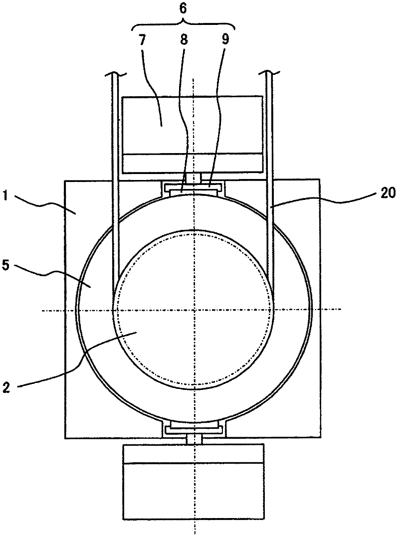
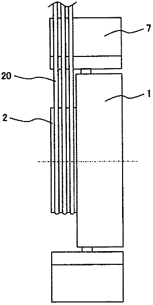
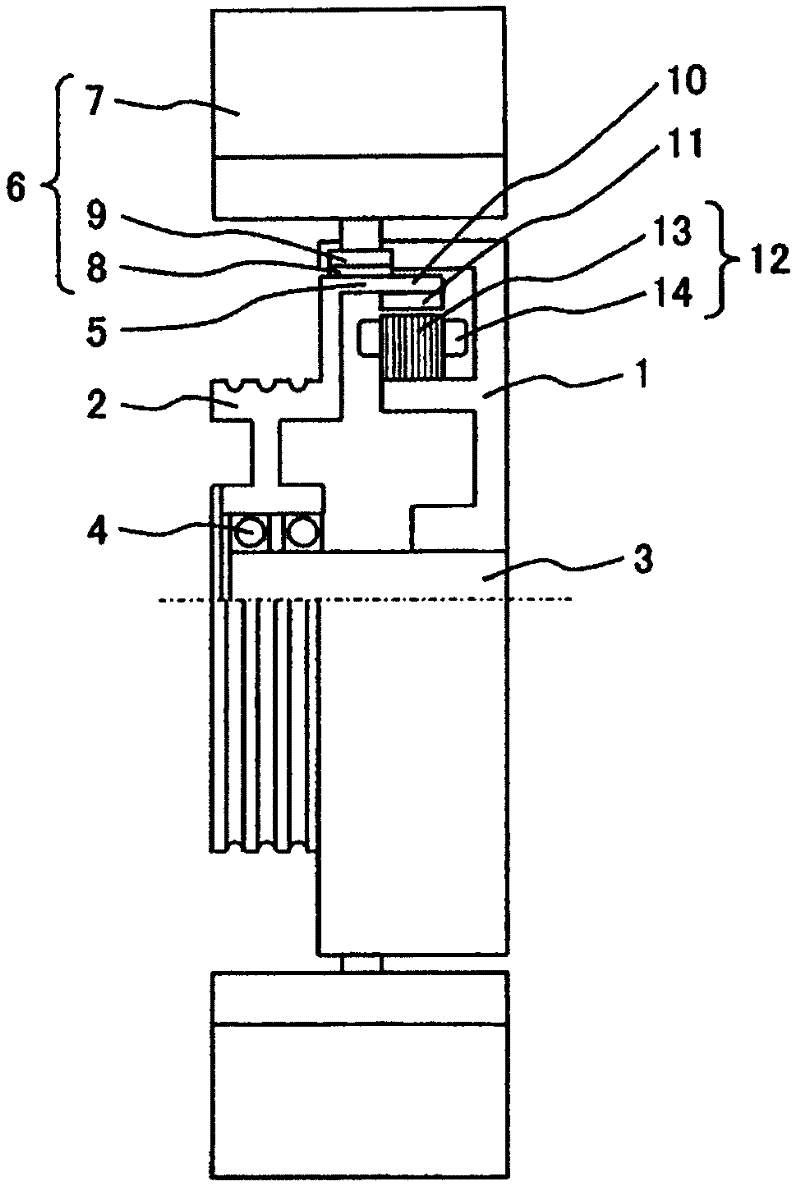
[0049] Figure 1 to Figure 3 A thin hoist for an elevator according to an embodiment of the present invention is shown, figure 1 is the main view, figure 2 is the side view, image 3 is a side view of a partial section. As shown in the accompanying drawings, the thin winch consists of a frame body 1, a sheave 2, a main shaft 3, a bearing 4, a brake drum 5, a rotor 10 of an electric motor, a stator 12, and an electromagnetic braking device 6. In addition to the above components, A rotation detector (not shown) and the like are also mounted inside the housing 1 .
[0050] The frame body 1 is made by forming a rough shape with cast iron, etc., and then machining the parts that need to have precise dimensions. The internal shape of the frame body 1 is a cylindrical shape with a bottom, so that it can A brake drum 5, a motor rotor 10, a stator 12, a bearing 4, a rotation detector, and the like are installed. The protruding part provided at the central part of the frame body ...
Embodiment 2
[0064] Figure 4 and Figure 5 It mainly shows other embodiments related to the fixing method between the electromagnetic braking device and the frame, and the same parts are denoted by the same symbols, and their descriptions are omitted.
[0065] In the above embodiments, the electromagnet 7 is directly fixed on the frame body 1 , but in this embodiment, the electromagnetic braking device 6 is mounted on the frame body through the fixing member 50 . At this time, if Figure 4 As shown, by providing the fixing member 50 as a thin fixing member that does not interfere with the sling 20 , it is possible to prevent the fixing member 50 from interfering with the sling 20 . Therefore, the electromagnetic braking device of the present invention does not include the fixing member 50 , and the electromagnetic braking device 6 is disposed in the area between the slings 20 , which is equivalent to an embodiment of the present invention.
Embodiment 3
[0067] Figure 7 to Figure 9 It mainly shows other embodiments of the constituent parts of the electromagnetic brake, and the same parts are denoted by the same symbols, and their descriptions are omitted.
[0068] As shown in the figure, the electromagnetic brake device 6 is mainly composed of an electromagnet 7, a brake spring 51, a brake pad 8, a brake pad support member 9 and an electromagnet support member 50. 14 iron cores and armatures facing each other across an air gap. The electromagnet supporting member 50 is configured to fix the iron core, and relatively move the armature when the brake operates. The armature is fixed with a pillar connected to the brake pad support member 9, and the brake pad support member 9 is equipped with a brake pad 8, through which the armature, the brake pad support member 9 and the brake pad 8 perform One action.
[0069] A plurality of brake springs 51 are arranged on the outside of the iron core. In order to maximize the outer diamet...
PUM
 Abstract
Description
Claims
Application Information
 - R&D Engineer
- R&D Manager
- IP Professional
- Industry Leading Data Capabilities
- Powerful AI technology
- Patent DNA Extraction
Browse by: Latest US Patents, China's latest patents, Technical Efficacy Thesaurus, Application Domain, Technology Topic, Popular Technical Reports.
© 2024 PatSnap. All rights reserved.Legal|Privacy policy|Modern Slavery Act Transparency Statement|Sitemap|About US| Contact US: help@patsnap.com


