Brake control device directly driven by permanent magnet synchronous motor for automatic staircase

A permanent magnet synchronous motor and escalator technology, applied in escalators, brake actuators, transportation and packaging, etc., can solve the problems of reducing manufacturing and maintenance costs, and the braking torque cannot meet the braking distance requirements at the same time, to achieve Reduce manufacturing and maintenance costs, promote wide application, and high efficiency

Inactive Publication Date: 2011-09-28
SHENYANG YUANDA INTELLECTUAL IND GRP CO LTD
View PDF6 Cites 6 Cited by
  • Summary
  • Abstract
  • Description
  • Claims
  • Application Information

AI Technical Summary

Problems solved by technology

[0004] The purpose of the present invention is to provide a braking control device for an escalator directly driven by a permanent magnet synchronous motor, which solves the problem that the same braking torque in the prior art cannot simultaneously meet the requirements for braking and stopping distances under no-load and full-load working conditions, In addition to retaining the advantages of stable transmission, high efficiency and low noise of permanent magnet synchronous motor drive, compared with

Method used


Image

  • Brake control device directly driven by permanent magnet synchronous motor for automatic staircase
  • Brake control device directly driven by permanent magnet synchronous motor for automatic staircase
  • Brake control device directly driven by permanent magnet synchronous motor for automatic staircase

Examples


Embodiment Construction

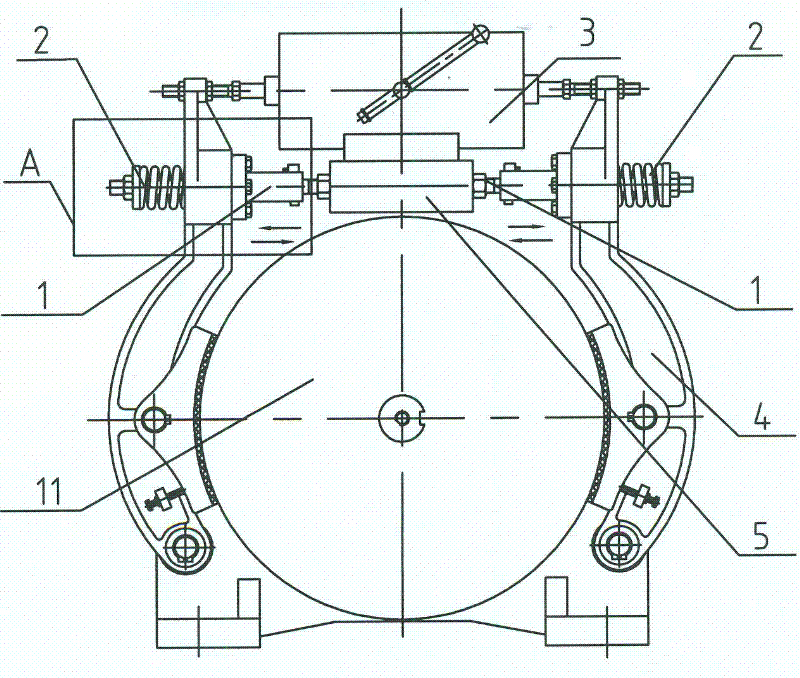
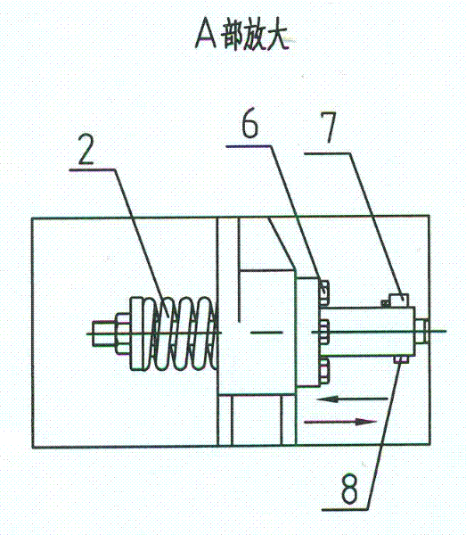
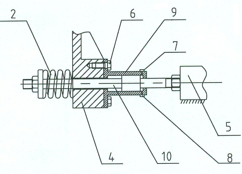
[0013] according to Figures 1 to 3 The specific structure of the present invention will be described in detail. The braking control device of the permanent magnet synchronous motor directly driving the escalator includes an electromagnetic brake 3, a brake arm 4 with a compression spring 2 and a brake shoe assembled on the outer periphery of the brake disc 11, a self-balancing cylinder 1 and the like. A self-balancing air cylinder 1 for controlling the braking torque of the braking arm 4 is arranged between the two ends of the fixing seat 5 of the electromagnetic brake 3 and the inner side of the braking arm 4 respectively. The cylinder body 9 of the self-balancing cylinder 1 is fixed on the inner side of the brake arm 4 through the connecting bolt 6 . One end of the piston rod 10 of the self-balancing cylinder 1 is connected to the end of the fixed seat 5, and the other end of the piston rod 10 is assembled on the outside of the brake arm 4 through the compression spring 2 ...


PUM


Abstract

The invention provides a brake control device directly driven by a permanent magnet synchronous motor for an automatic staircase, for solving the problem that in the prior art, the same brake moment cannot satisfy the brake distance demands under no load and full load conditions. The brake control device comprises an electromagnetic brake and brake arms, wherein the brake arms are provided with a compression spring and a brake shoe and are assembled at the circumference of a brake disc. The brake control device is technically characterized in that: self-balanced cylinders for controlling the brake moment of the brake arm are installed between two ends of a fixed seat of the electromagnetic brake and the inner side of the brake arm; the cylinders are fixed at the inner side of the brake arm through a connection bolt; one end of a piston rod is connected with the end of the fixed seat; and the other end of the piston rod is assembled on the outer side of the brake arm through the compression spring and a fastening part. Compared with the like brake control device, the brake control device in the invention is more rational in design, simpler and compacter in structure, more reliable in brake, more convenient to control and regulate, and easier to satisfy demands of the standard brake distance and brake reducing demands under the no load and full load conditions; and the brake control device notably reduces the manufacturing and maintenance cost.

Description

technical field [0001] The invention relates to a braking control device for an escalator, in particular to a self-balancing cylinder arranged at the compression spring of the working brake to gradually change the braking torque and control the force exerted by the compression spring of the working brake on the brake disc. The permanent magnet synchronous motor directly drives the brake control device of the escalator, and is also suitable for the brake control of the moving walk. The invention belongs to the technical field of braking control of escalators and moving walkways. Background technique [0002] According to the requirements of the braking distance in the new European standard EN115-1:2008 "Safety Regulations for the Manufacture and Installation of Escalators and Moving Walks", the working brake should be able to effectively decelerate and stop the escalators and moving walks with braking loads. and keep it still. The deceleration should not exceed 1m / s 2 , an...

Claims


Application Information

Patent Timeline
IPC IPC(8): B66B25/00F16D65/18
Inventor 李振才王岩卿于凤军
Owner SHENYANG YUANDA INTELLECTUAL IND GRP CO LTD
Why Eureka
Try Eureka