Compact roller drawing frame and spinning machine including same

A technology for drawing frames and spinning machines, applied in spinning machines, textiles, papermaking, drafting equipment, etc., can solve problems such as too large coverage area, and achieve the effect of compact structure

Inactive Publication Date: 2011-09-28
ROTORCRAFT SA (PTY) LTD
View PDF1 Cites 0 Cited by
  • Summary
  • Abstract
  • Description
  • Claims
  • Application Information

AI Technical Summary

Problems solved by technology

[0003] A disadvantage of these prior art roller draw frames is, for example, the long extent or the excessively large footprint they form in the running direction of the sliver to be drawn.

Method used


Image

  • Compact roller drawing frame and spinning machine including same
  • Compact roller drawing frame and spinning machine including same
  • Compact roller drawing frame and spinning machine including same

Examples


Embodiment Construction

[0032] It should be understood that components having the same and / or similar functions are identified with similar reference numerals in the figures.

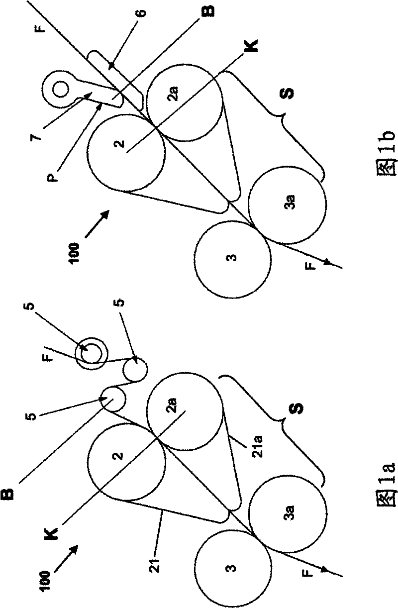
[0033] see now Figure 1a, shows a diagrammatic side view of a first embodiment of a roller draw frame 100 according to the invention showing the passage of a single spinning position, ie a single sliver F in the direction indicated by the arrows. The roll draw frame 100 comprises an input roll pair 2 / 2a and an output roll pair 3 / 3a forming a drafting zone S, between which the overall drafting of the sliver F is effected. The input roller pair 2 / 2a is wound by a drafting belt 21 / 21a (top belt / bottom belt) extending into the drafting zone S.

[0034] No pre-drawing zone is provided as in the prior art. Just before entering the drafting zone S, the sliver F supplied for compaction is lightly tensioned by a braking device having, for example, three sheaves 5 . The desired pre-stretching is achieved by the winding friction betw...


PUM


Abstract

A compact roller drawing frame and a spinning machine including the same. The invention provides a roller drawing frame 100 for drawing at least a short fiber strip (F), characterized in that a drawing region (S) on which the strip (F) is wholly drawn is only composed of two pairs of rollers (2 / 2a, 3 / 3a) and the strip is wholly drawn between two pairs of rollers (2 / 2a, 3 / 3a).

Description

technical field [0001] The invention relates to a roll draw frame for drawing at least one stapled sliver according to the preamble of claim 1 and also to a spinning machine comprising at least one roll draw frame. Background technique [0002] This type of roller draw frame is used to draw at least one sliver (roving, top roving) and preferably a plurality of such slivers comprising staple fibers (such as cotton fibers and / or man-made fibers) by known methods and devices to desired fineness. The sliver to be drawn is conveyed in a specific conveying (running) direction through a roller draw frame which, in the state of the art, comprises a plurality of pairs of rollers and is formed as several rollers between individual roller pairs. The overall drafting of a local drafting part. One such roll draw frame is known, for example, from German patent DE 100 52 878 A1, which incorporates three pairs of rolls for drafting. At the end of this conventional roller draw frame, the ...

Claims


Application Information

Patent Timeline
Patent Type & Authority Applications(China)
IPC IPC(8): D01H5/26D01H5/70D01H5/72
CPCD01H5/72D01H5/26D01H5/74
Inventor 汉斯・沙赫勒克尔彼得・施维尔
Owner ROTORCRAFT SA (PTY) LTD
Why Eureka
Try Eureka