
Method and device for lubricating false-twisted yarns with oil

A false-twisted silk and oil-lubricated technology, used in textiles and papermaking, can solve problems such as high friction, single chemical fiber breakage, single fiber chemical fiber breakage, etc., to improve consistency, prevent fluff or yarn breakage, and improve The effect of uniformity

Inactive Publication Date: 2011-09-28
绍兴华裕纺机有限公司
View PDF5 Cites 2 Cited by
  • Summary
  • Abstract
  • Description
  • Claims
  • Application Information

AI Technical Summary

Problems solved by technology

There are some defects in the original false-twisted yarn production process: 1. The false-twisted yarn runs upwards after winding several circles on the horizontal pin of the false-twisted rotor. False twisted yarn is composed of multi-F number of chemical fiber single fibers. At this time, because the false twisted yarn runs around the horizontal pin of the false twist rotor for several turns, the friction force is relatively large, causing several single fiber chemical fiber yarns to break and produce wool.
2. In the process described in 1 above, sometimes the frictional force of false twisted yarn is so large that all F-number chemical fiber single fibers will break, resulting in broken yarn
Therefore, for a long time, no one has ever proposed to change it to make up for the defects of the old technology.

Method used


Image

  • Method and device for lubricating false-twisted yarns with oil
  • Method and device for lubricating false-twisted yarns with oil
  • Method and device for lubricating false-twisted yarns with oil

Examples


Embodiment 1

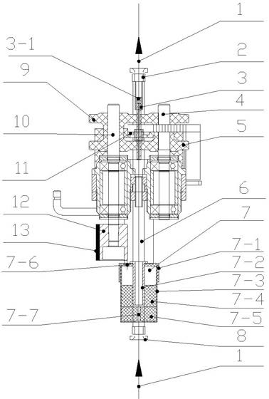
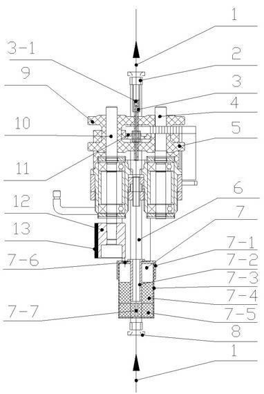
[0024] Such as figure 1 A false twist silk oil lubricating device shown is installed below the false twister. In this embodiment, the oil lubricating device adopts an oiler 7, and the oiler 7 is installed on the lower column 6 of the false twister to be connected with the false twister. into one.

[0025] The false twister includes a yarn guide 2, a false twist rotor 3, a driven shaft 4, a driven wheel 5, a lower column 6, a lower yarn guide 8, a driving wheel 9, and a driving shaft 10, in which: a pulley 12 and a dragon belt 13 linkage connection, driving shaft 10 is linked with pulley 12, driving wheel 9 is linked with driving shaft 10, false twist rotor 3 is adsorbed and positioned between driving wheel 9 and driven wheel 5 by magnet 11, false twist rotor 3 and driving wheel 9 linkage connection, the driven wheel 5 is linked with the false twist rotor 3, the driven wheel 5 is installed on the driven shaft 4, the oiler 7 is installed on the lower column 6, the lower yarn gu...

Embodiment 2

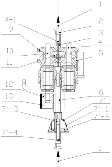
[0029] figure 2 Another embodiment of the present invention is shown, and its oil lubrication structure and method are the same as those in Embodiment 1, the difference is that the oiler 7' having a different structure from the oiler 7 in Embodiment 1 is used, specifically as figure 2 As shown, the oiler 7' is installed on the lower column 6, including a closed oiler housing 7'-1, in which the lubricating oil 7'-2 is filled in the oiler housing 7'-1, and the oil seepage channel 7'-3 is set In the middle of the oiler casing 7'-1, the axis of the oil seepage channel 7'-3 is consistent with the running track of the wire, the ceramic part 7'-4 is arranged below the oil seepage channel 7'-3, and the oil seepage channel 7'-3 '-3 adopts a honeycomb structure, through the honeycomb micropores on the oil seepage channel 7'-3, the lubricating oil 7'-2 in the oiler shell 7'-1 seeps out, so that the oil from the lower wire guide 8 The incoming false twisted yarn 1 enters the oil seepag...


PUM


Abstract

The invention discloses a method and device for lubricating false-twisted yarns with oil, belonging to the textile technical field. The device is characterized by comprising an oil feeder, wherein the oil feeder is installed below a false twister and is used for lubricating false-twisted yarns with oil before the false-twisted yarns enter into a false-twist rotor. After being lubricated by the device with oil, the false-twisted yarns enter into the false-twist rotor to be false-twisted. The friction of the false-twisted yarns is reduced in the false-twist process so as to achieve uniform and full false twist degree of the false-twisted yarns and effectively reduce the end breakage rate in the yarn false-twist process. The invention provides a new method and process device for production of the false-twisted yarns.

Description

Technical field: [0001] The invention relates to a false twist silk oil lubrication method and a device thereof, belonging to the technical field of textile machinery. Background technique: [0002] False twisted silk is a variety of modern silk thread. It is used to weave cloth, and its style is similar to real silk fabric, also known as imitation silk. It is usually obtained by false-twisting chemical fiber filaments with a false twister. [0003] At present, the false-twisting process used for a long time in this field is that the pre-heated false-twisting yarn directly enters the false-twisting rotor in the false-twisting device, and after the false-twisting yarn is wound several times on the horizontal pin in the false-twisting rotor, it continues to run on. This is carried out under the condition that the false twist rotor rotates at a high speed of hundreds of thousands of revolutions per minute. At this time, the false twist yarn is curled into a spiral state and ...

Claims


Application Information

Patent Timeline
Patent Type & Authority Applications(China)
IPC IPC(8): D01H13/30D01H7/92
Inventor 刘光容朱爱萍
Owner 绍兴华裕纺机有限公司
Learn More