Roller transmission device

A transmission device and roller technology, applied in the direction of transmission device, belt/chain/gear, mechanical equipment, etc., can solve the problems of low efficiency, cannot be made into high-power and low-speed motor, etc., and achieves simple structure, coaxial output, The effect of reducing the radial force component

Inactive Publication Date: 2011-09-28
于杰 +1
View PDF0 Cites 4 Cited by
  • Summary
  • Abstract
  • Description
  • Claims
  • Application Information

AI Technical Summary

Problems solved by technology

Therefore, the efficiency is not high, and it cannot be made into a high-power low-speed motor
Currently known reducers do not have a low-speed high-torque motor that can output high torque and can be directly integrated with the motor

Method used


Image

  • Roller transmission device
  • Roller transmission device
  • Roller transmission device

Examples


Embodiment Construction

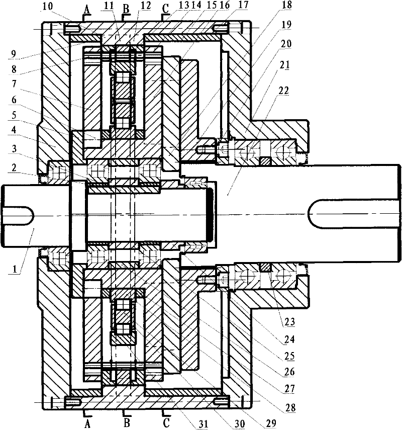
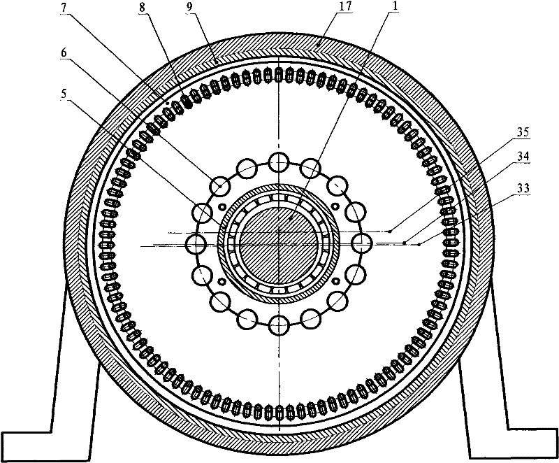
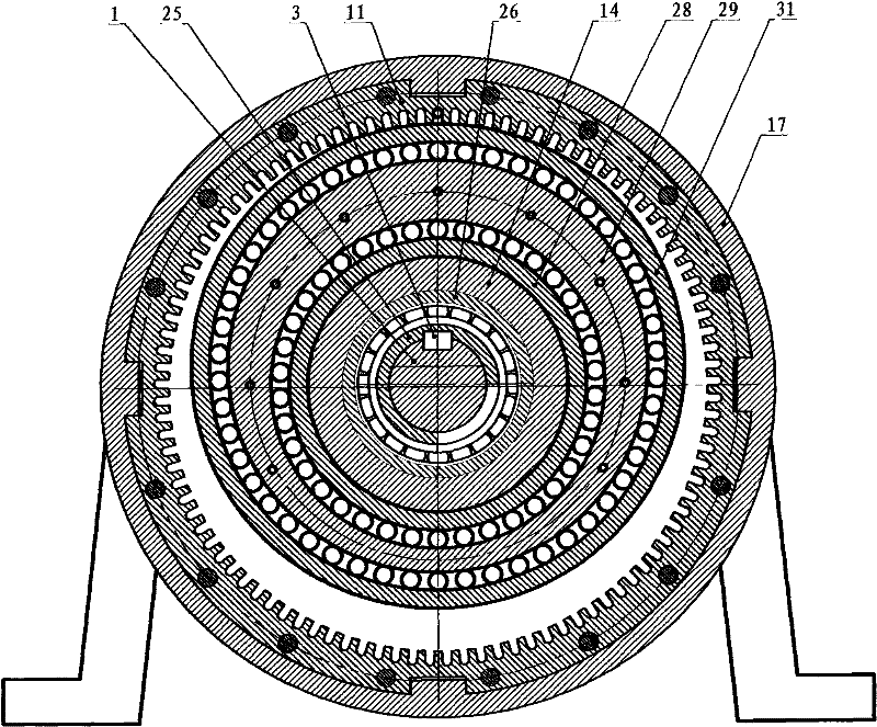
[0026] Examples of the present invention figure 1 , figure 2 , image 3 , Figure 4 Shown:

[0027] The input shaft [1] is formed by superimposing the cylinder at the left end, the shaft shoulder and the cylinder at the right end. All cylinders except the shaft shoulder are machined with keyways. A groove for mounting a shaft retaining ring is machined at the far right end. The input shaft can also be directly made into a shaft shoulder, and the centerlines of the left and right ends coincide, and the centerlines of the supporting left and right sheave positions do not coincide with the centerlines of the left and right ends. Using this measure can cancel the eccentric sleeve [2].

[0028] The eccentric sleeve [2] is superimposed by an outer cylinder and an inner hole whose centerlines do not overlap, and a keyway is processed in the hole.

[0029] Flat key [3] is installed on the input shaft [1] and connects the hexahedron of eccentric sleeve [2].

[0030] Left cover...


PUM


Abstract

The invention discloses a roller transmission device, and relates to a device for transmitting power through rollers in groove wheels and groove rings. The device has the characteristics that the large speed ratio range, small volume, small pressure angle, high-speed input and low loading of a bearing are ensured, the motion mode of the rollers is pure rolling, and multiple rollers participate in the work simultaneously. The device provided by the invention is used for speed change of source power; the number difference of the groove wheels and groove rings can be one or more than one; the axial spaces of the groove rings and the groove wheels are not coincident; the rollers move in the radial grooves of the groove wheels and the groove rings; the eccentric direction of a double-layer eccentric bearing is the same with that of the groove wheels; when the rollers are delivered to the openings of the groove rings by the double-layer eccentric bearing, the rollers perform pure rolling along the side surfaces of the radial grooves of the groove wheels and the groove rings; at the same time, the double-layer eccentric bearing is not contact with the rollers any more; the rollers break away from the radial grooves of the groove rings under the action of an elastic ring at the instant of leaving of the groove rings; and the elastic ring implies force to the rollers to enable the rollers to always maintain the radial force, thus the rollers except for the roller participating in the power transmission are all arranged at the bottoms of the groove wheels.

Description

technical field [0001] The invention relates to a device for transmitting power through a grooved wheel and a roller in a grooved ring. The movement of the roller in the centripetal groove of the sheave and groove ring is pure rolling. The designer can change the relevant parameters to get the purpose of multi-roller participating in the work. Although only a pair of sheaves, grooved rings and some rollers are used in this device to participate in the movement, the transmission ratio can take an integer value from four to hundreds. The included angle between the movement direction of the sheave and the force direction of the device is a negative value, and the angle is far smaller than the gear pressure angle. The device shown in the figures of this specification has a pressure angle of less than one degree. The present invention can be used for changing the speed of the prime mover, and can also be used for a large-torque floating shaft coupling. Background technique ...

Claims


Application Information

Patent Timeline
Patent Type & Authority Applications(China)
IPC IPC(8): F16H27/04
Inventor 于杰于泓
Owner 于杰
Why Eureka
Try Eureka