Fast-heating type water heating device

A water heating device, fast heating technology, applied in water heaters, fluid heaters, lighting and heating equipment, etc., can solve the problems of reduced reaction sensitivity, oscillation, large distance, etc., to achieve low flow resistance and controllable temperature Good performance and high thermal efficiency

Inactive Publication Date: 2011-09-28
宁波市塞纳电热电器有限公司
View PDF10 Cites 11 Cited by
  • Summary
  • Abstract
  • Description
  • Claims
  • Application Information

AI Technical Summary

Problems solved by technology

In general, the thermistor will be arranged near the outlet pipe, so that the corresponding relationship between the thermistor signal and the outlet water temperature is more stable, but if it is too close to the outlet pipe, the advance of the control is not enough. When the temperature is found to be too high, adjust it , will cause oscillation and fail to achieve the control target. In addition, the thermistor is the most sensitive sensor when the electric heating film is empty-burned. The temperature rises rapidly, so that the control system can judge the power supply of th

Method used


Image

  • Fast-heating type water heating device
  • Fast-heating type water heating device
  • Fast-heating type water heating device

Examples


Embodiment 1

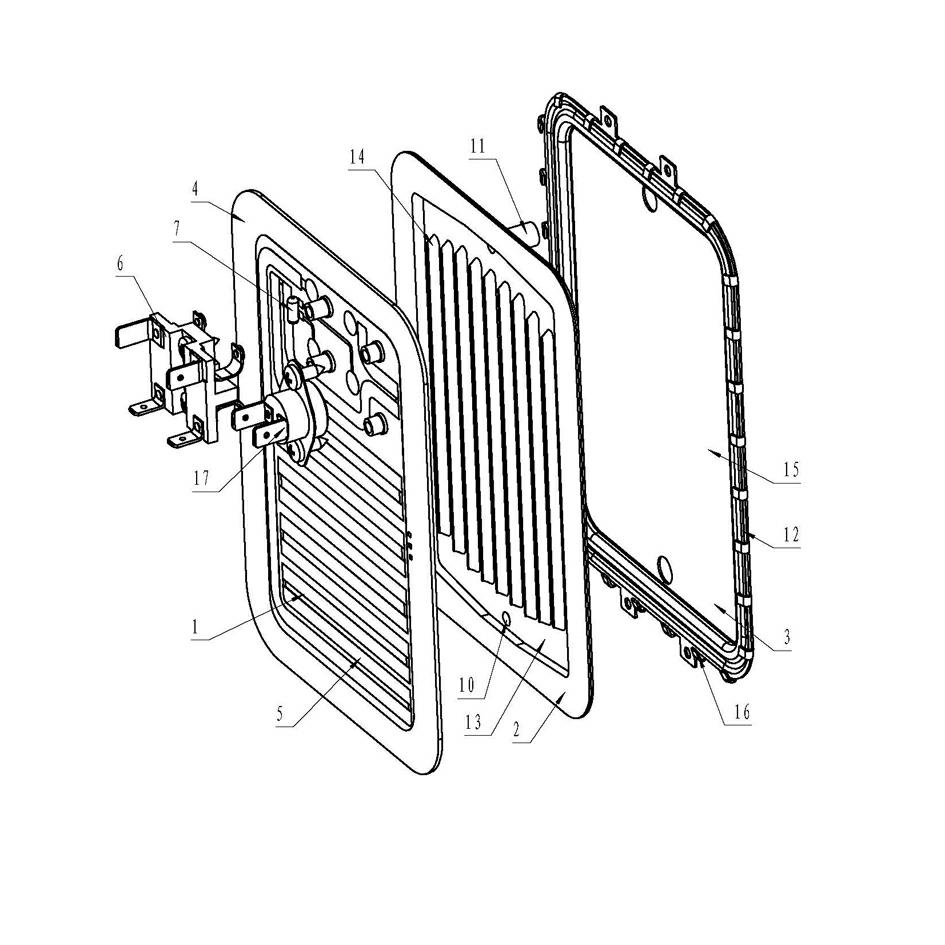
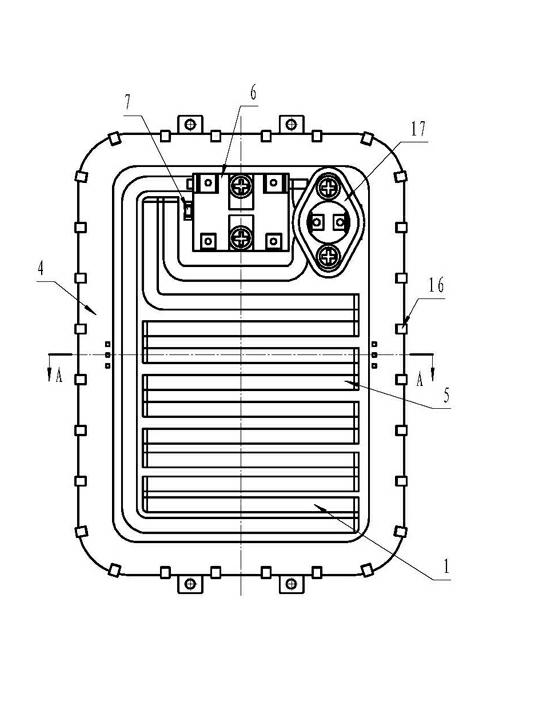
[0019] The embodiment of the present invention is mainly composed of an electric heating film heating plate 1, a water channel plate 2, a heating body rear plate 3, a temperature controller 17, a thermistor 7, a water inlet 10 (pipe), a water outlet 11 (pipe), and a control circuit. The electrothermal film heating plate 1 and the heating body rear plate 3 clamp the water channel plate 2 through several tooth-shaped installation buckles 16 around the heating body rear plate 3, and are bent and sealed as a whole. A water channel cavity 9 that allows water to flow is formed between the water channel grid 14 and the electric heating film heating plate 1. The shape of the cavity guides the flow of water. The water inlet 10 (pipe) and the water outlet 11 (pipe) are located The upper and lower ends of 2 are drawn from the water channel plate 2 through the heating body rear plate 3. The water channel plate 2 is rectangular, and the grille 14 arranged on it is S-shaped, forming a series...

Embodiment 2

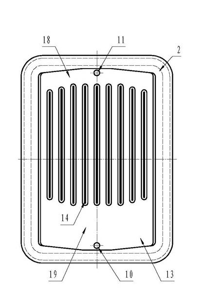
[0021] The water channel plate 2 described in this embodiment is rectangular, and the grille 14 arranged on it is in the shape of a vertical line, forming a longitudinal parallel pipeline, and a laterally arranged diversion channel cavity 19 is formed at the lower end of the grille 14 to connect with the water inlet 10, On the upper end of the grille 14, there is a horizontally arranged confluence channel cavity 18 connected to the water outlet 11; the longitudinal linear grille 14 arranged on the rectangular waterway plate 2 is provided with a transverse diverter at the lower end of the grille 14. The upper and lower height of the waterway cavity 19 (that is, the distance from the water inlet to the bottom of the grid) is 60 mm, and the upper and lower height of the horizontal confluence waterway cavity 18 (that is, the distance from the water outlet to the top of the grid) is set at the upper end of the grid 14 is 8 mm; The vertical linear grid 14, wherein the width of each w...

Embodiment 3

[0023] The water channel plate 2 described in this embodiment is rectangular, its lower area is a cavity, and its upper area is provided with a grid 14. The grid 14 is S-shaped to form a series of water channel cavities 9, and its cross section is rectangular or trapezoidal. The section width is 6.6mm, the height is 2.7mm, the cavity length of the lower area of ​​the water channel plate 2 is 64mm; the electrothermal film heating plate 1 is curved, so that it forms a local Gap, the electrothermal film heating plate 1 and the grid (14) have partial contact around the waterway plate, the length of the close contact between the electrothermal film heating plate 1 and the grid 14 is 3% of the total length of the grid 14, and the remaining 97% of the length is matched as Clearance fit, the best clearance is 0.5-0.8mm; the thermistor 7 is set on the electrothermal film heating plate 1, the distance between the center of the thermistor 7 and the water outlet 11 is 20mm, and the distanc...


PUM

PropertyMeasurementUnit
Heightaaaaaaaaaa
Heightaaaaaaaaaa
Section widthaaaaaaaaaa

Abstract

The invention discloses a fast-heating type water heating device. The invention relates to a water heating device, in particular to the fast-heating type water heating device which performs heating by using a stainless steel substrate electric heating film and is applied to an instant electric kettle. The fast-heating type water heating device mainly comprises an electric heating film heating plate, a water channel plate, a heating body rear plate, a temperature controller, a thermo-sensitive resistor, a water inlet, a water outlet and a control circuit, wherein the electric heating film heating plate (1) and the heating body rear plate (3) clamp the water channel plate (2) and are connected into a whole by a connecting piece or in a welding sealing mode; a grating (14) is arranged on thewater channel plate (2); a water channel cavity (9) capable of making water flow is formed between the grating (14) on the water channel plate (2) and the electric heating film heating plate (1); theshape of the cavity guides a flowing direction of the water; and the water inlet and the water outlet are positioned at upper and lower ends of the water channel plate and led out from the water channel plate by the heating body rear plate. The fast-heating type water heating device is characterized in that: the electric heating film heating plate (1) is curved and in clearance fit with the waterchannel plate (2), so a local clearance is formed at a joint between the electric heating film heating plate (1) and the grating (14) which is arranged on the water channel plate (2). The invention has the advantages that: compared with the prior art, the fast-heating type water heating device is higher in heat efficiency, better in temperature controllability and lowest in flowing resistance of a heating body; and a water outlet temperature can be controlled to be above 95 DEG C during fast heating.

Description

technical field [0001] The invention relates to a water heating device, in particular to a fast-heating water heating device for an instant electric kettle which uses a stainless steel substrate electric heating film to generate heat. Background technique [0002] After years of development, there have been many types of electric kettles. In recent years, in order to solve the problem of boiling water quality caused by repeated heating of water by a galled heating kettle, people have invented an instant electric kettle device by using the existing electric heating film technology. The cold water can be heated by a water heating body to become hot water, and then flow out through the water nozzle, so that the hot water can be used immediately, which is not only convenient to use, but also saves electric energy, and is safe and hygienic. Such as: a kind of name disclosed in Chinese patent literature on January 31, 2001 is called " instantaneous water heater " patent announceme...

Claims


Application Information

Patent Timeline
IPC IPC(8): F24H1/10F24H9/18A47J27/21
Inventor 章国庆蔡建立冯玉江龚胤杰
Owner 宁波市塞纳电热电器有限公司
Why Eureka
Try Eureka