Light source collector structure

A collector and light source technology, applied in the field of light source collectors, can solve problems such as the reduction of photoelectric conversion efficiency, and achieve the effect of effective photoelectric conversion

Inactive Publication Date: 2011-09-28
PACIFIC SPEED
View PDF2 Cites 0 Cited by
  • Summary
  • Abstract
  • Description
  • Claims
  • Application Information

AI Technical Summary

Problems solved by technology

However, forming the saw-toothed interval or grating on these lenses still has the problem of aligning the photoelectric conversion unit with the lenses with the saw-toothed interval or grating, that is, when it cannot be precisely aligned, it still causes Decrease in Photoelectric Conversion Efficiency

Method used


Image

  • Light source collector structure
  • Light source collector structure
  • Light source collector structure

Examples


Embodiment Construction

[0019] In order to fully understand the purpose, features and effects of the present invention, the present invention will be described in detail by means of the following specific embodiments and accompanying figures, as follows:

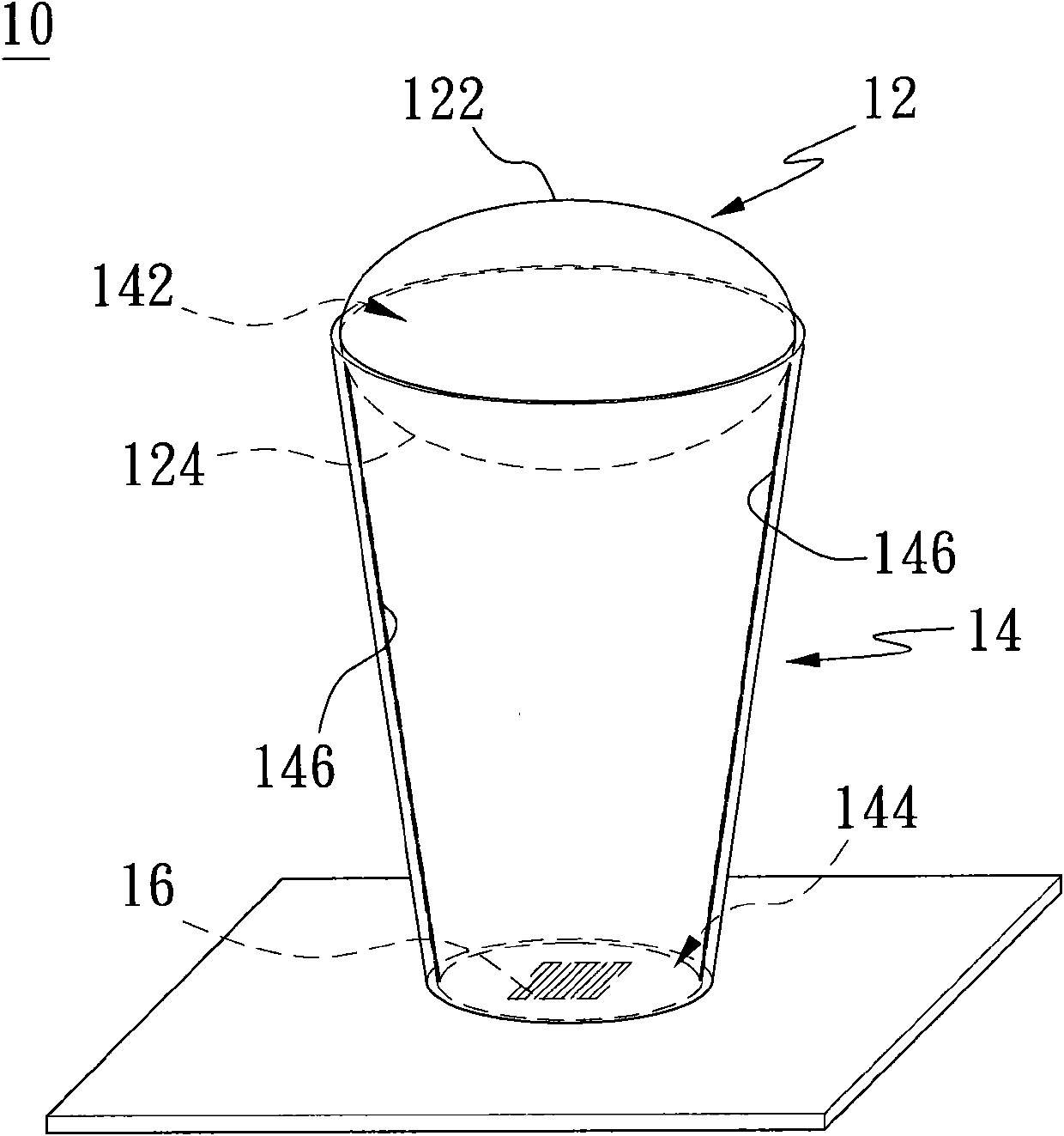
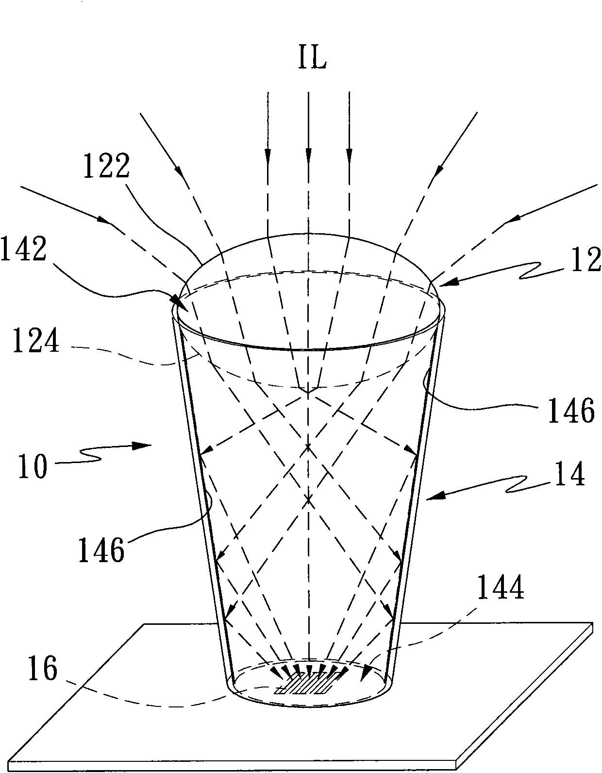
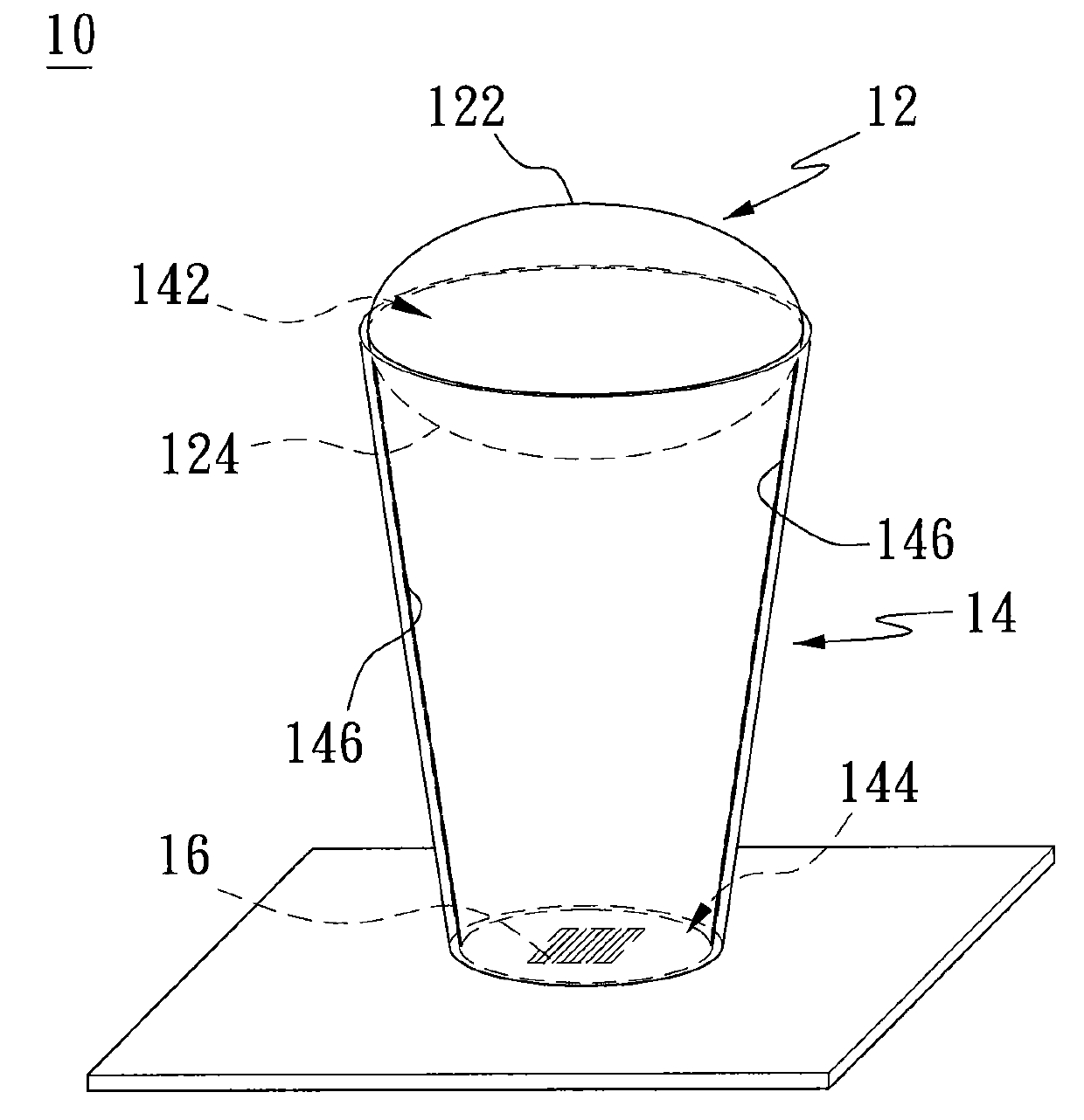
[0020] refer to figure 1 , is a schematic structural diagram of a light source collector according to an embodiment of the present invention. In this embodiment, the light source collector structure 10 includes a light collecting unit 12 , a light collecting unit 14 and a receiving unit 16 . The light concentrating unit 12 has an incident surface 122 and an outgoing surface 124. For example, the light concentrating unit can be spherical or elliptical, and the elliptical shape is used for illustration here. In addition, the material of the light concentrating unit 12 has a high temperature resistance coefficient or a high light transmittance coefficient, which is used to make the incident light source not only have high penetration, but also not ca...


PUM


Abstract

The invention discloses a light source collector structure, which is used for collecting a light source and comprises a light condensing unit, a light collecting unit and a receiving unit, wherein the light condensing unit is provided with an incidence plane and an emergence plane; the light source enters the light condensing unit from the incidence plane; the light condensing unit changes an optical path distance and the light travelling direction of the light source to make the light source uniformly transmitted to the emergence plane; the light collecting unit is provided with two end faces; a reflecting layer is arranged in the light collecting unit; the light condensing unit is arranged on one end face of the light collecting unit and used for receiving the light source from the emergence plane; the light source which emerges from the emergence plane is reflected to the other end face of the light collecting unit through the reflecting layer; and the receiving unit is arranged on the other end face of the light collecting unit and used for receiving the light source which emerges from the light collecting unit and further carrying out photoelectric conversion to convert the light energy of the light source into electric energy.

Description

technical field [0001] The invention relates to a light source collector, more particularly to a light source collector structure with high light collection efficiency. Background technique [0002] In the known technology, the photoelectric conversion device is composed of a plurality of lenses and corresponding photoelectric conversion units for focusing an incident light source on the photoelectric conversion unit so that light energy is converted into electrical energy. However, when the incident light source is focused to the photoelectric conversion unit, there is still a gap between the lens and the photoelectric conversion unit, so there is still an alignment problem. In addition, although the incident light source can be focused on the photoelectric conversion unit through these lenses, the incident light source may not be uniformly focused on the photoelectric conversion unit by these lenses due to other factors, for example, these lenses contain impurities, It wi...

Claims


Application Information

Patent Timeline
Patent Type & Authority Applications(China)
IPC IPC(8): G02B17/08H02N6/00H02S40/22
CPCY02E10/50
Inventor 林健峯黄成宇古德垲林传宜
Owner PACIFIC SPEED
Why Eureka
Try Eureka