
Method for realizing rapid path switching and apparatus thereof

A fast path and path technology, applied in the field of network communication, can solve the problems of slow response and long switching time, and achieve the effect of shortening the speed and reducing the interruption time.

Active Publication Date: 2011-09-28
NEW H3C TECH CO LTD
View PDF5 Cites 26 Cited by
  • Summary
  • Abstract
  • Description
  • Claims
  • Application Information

AI Technical Summary

Problems solved by technology

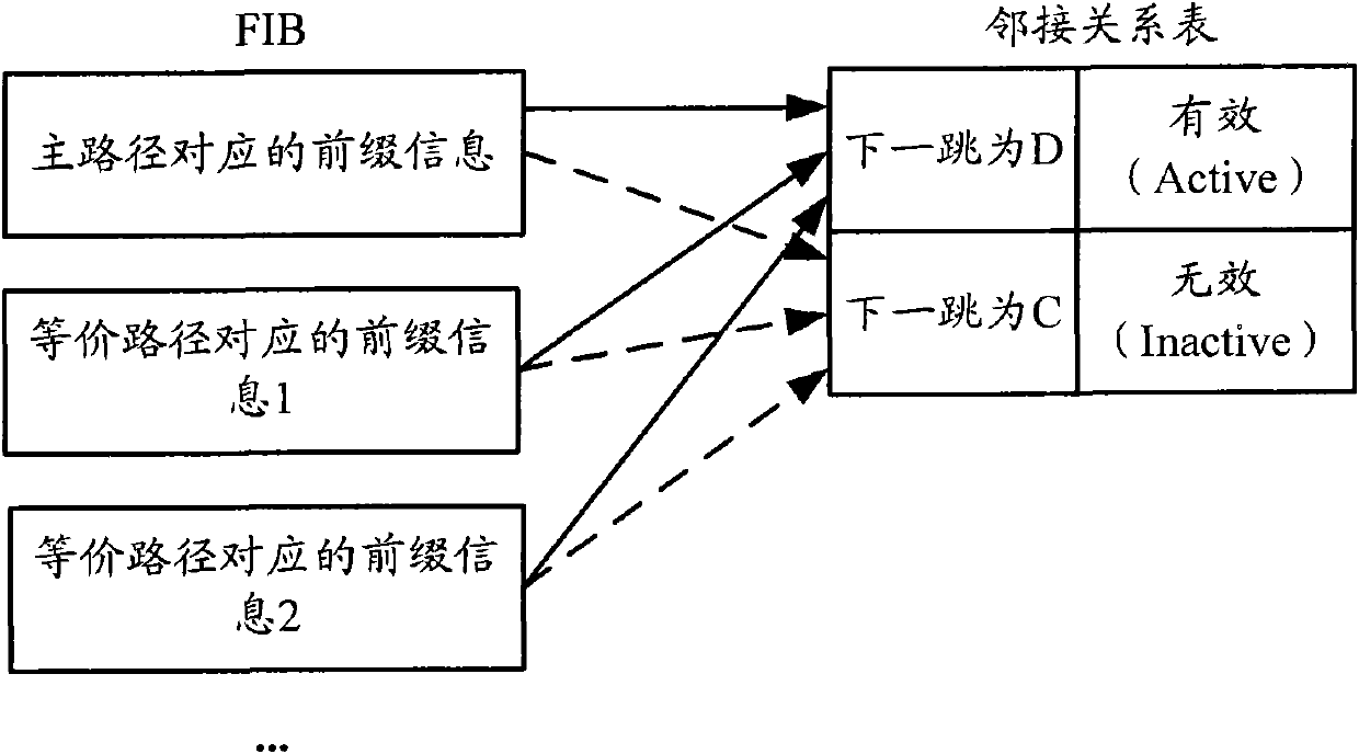
It can be seen that when the path switching is based on the next hop active / standby switching, the FIB of the control plane needs to be refreshed, the response is slow, and the switching takes a long time, especially when there are multiple equal-cost paths on the main path ,like Figure 2b As shown, the prefix information corresponding to multiple equivalent paths in the FIB needs to be updated one by one, and the defect is more obvious

Method used


Image

  • Method for realizing rapid path switching and apparatus thereof
  • Method for realizing rapid path switching and apparatus thereof
  • Method for realizing rapid path switching and apparatus thereof

Examples


Embodiment 1

[0040] still with figure 1 The schema shown is an example, Figure 4 The detailed method flowchart provided by the present invention under this framework, such as Figure 4 As shown, the method implemented in routing device B may include the following steps:

[0041] Step 401: After the route is calculated for the destination E, a forwarding entry corresponding to the route is formed.

[0042]Usually, according to the routing strategy set on the routing device, it can be determined that the route learned on each interface corresponds to the master-backup relationship between each path, that is, the calculation and designation of the master-backup path in the present invention is performed in advance. In this step, the route calculated for the destination E may include the routing information of the main path and the routing information of the backup path, and may further include the equivalent path of the main path. The situation about the equivalent path will be described i...

Embodiment 2

[0072] by Figure 7 The architecture shown is taken as an example. In this architecture, among the routes learned by routing device B, there are two other equal-cost paths of path B-D, namely path B-F-D and path B-G-D, and path B-C-D can be the backup of the above three equal-cost paths path.

[0073] for Figure 7 In the architecture shown, after the route is calculated for the destination E in step 401, since the route at this time includes each equivalent path and the backup path with each equivalent path, the formed forwarding table entry includes each equivalent path routing information, next hop information, and next hop status. Wherein, the routing information includes the destination IP address and the outgoing interface index. exist Figure 7 In the shown architecture, the formed forwarding entries may be as shown in Table 2.

[0074] Table 2

[0075] routing information

next hop information

next hop status

Routing information correspondi...


PUM


Abstract

The invention provides a method for realizing rapid path switching and an apparatus thereof. Next hop information and next hop state, which are main / standby paths for each other, are maintained through forming a virtual next hop (VN) table which aims at destination. Prefix information corresponding to the destination in a forwarding information base (FIB) is pointed to the VN table so that when there are changes in the next hop information, the prefix information in the FIB does not need to be modified point by point because there is no change in the point of the prefix information. The next hop information in the updated VN table only needs to be sent to a drive so that the drive can update the next hop information which is written-in hardware. Even if there are a plurality of equal-cost multipath routings (ECMP), the VN table only needs to be updated once and then sends the information so as to realize switching of a plurality of paths. The prefix information in the FIB does not need to be modified point by point. Therefore, speed of switching paths is substantially raised and interruption time in traffic can be reduced.

Description

technical field [0001] The invention relates to the technical field of network communication, in particular to a method and device for realizing fast path switching. Background technique [0002] In order to meet the extremely high routing speed, the current routing protocols adopt many new technologies in fast convergence. However, the emergence of new network services such as voice and video places higher requirements on the traffic interruption time. The basic principle of IP fast rerouting (FRR) is: calculate the backup path in advance, once a fault is detected, immediately start the backup path to guide the forwarding, so that the traffic interruption time is shortened to the sum of the time for detecting adjacent faults and the time for replacing the failed route with the backup path , which solves the time for routing calculation and synchronization between forwarding table boards, and greatly shortens the traffic interruption time. [0003] figure 1 It is a schemat...

Claims


Application Information

Patent Timeline
IPC IPC(8): H04L12/56H04L12/46H04L29/06H04L12/701
Inventor 韩立峰
Owner NEW H3C TECH CO LTD
Learn More