
Stable sleeve-dropping method for moveable sleeve of hot milling machine

A hot-rolling mill and drop-in technology, which is applied in the direction of metal rolling, metal rolling, bending workpieces, etc., can solve the problems that cannot be controlled, unsolved, and cannot avoid the influence of rolling mill speed changes, etc., to achieve safe and accurate tracking closed-loop Effects of controlling, preventing tail flicking, and avoiding mechanical impact

Inactive Publication Date: 2013-01-23
SHANGHAI MEISHAN IRON & STEEL CO LTD
View PDF2 Cites 0 Cited by
  • Summary
  • Abstract
  • Description
  • Claims
  • Application Information

AI Technical Summary

Problems solved by technology

[0010] The above-mentioned 200710061425.3 only uses the load head and tail signals of the rolling mill to control the lifting and falling sleeves of the looper, which cannot avoid the influence caused by the speed change of the rolling mill; while the focus of 03135885.3 is to prevent the impact of the looper on the base when the looper falls
Its control idea is to determine a more reasonable trapping point, but it does not solve the problem of how to correlate the loop amount control with the looper motion control, so it is still impossible to achieve a smooth control of the trapping

Method used


Image

  • Stable sleeve-dropping method for moveable sleeve of hot milling machine
  • Stable sleeve-dropping method for moveable sleeve of hot milling machine

Examples


Embodiment 1

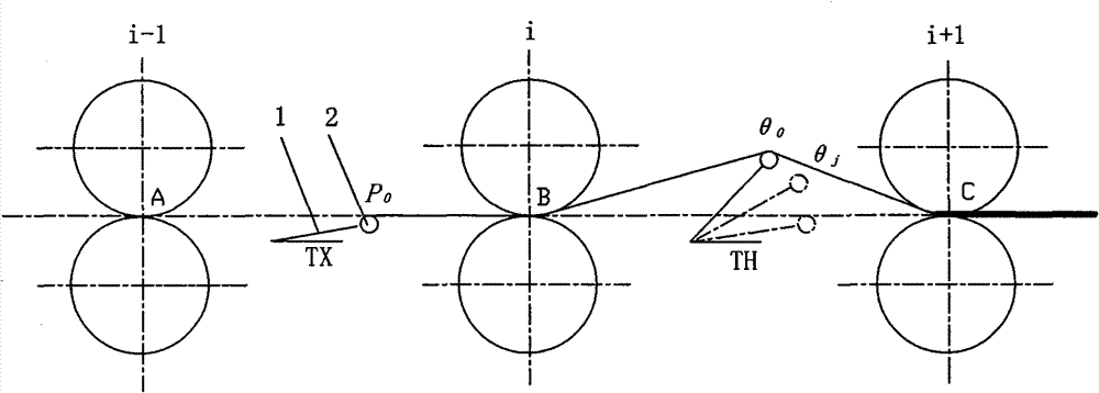
[0023] The method for the hot-rolling mill looper to fall smoothly in this embodiment is in the upstream frame i-1, the middle frame i and the downstream frame i+1 arranged in sequence, the upstream frame i+1 and the middle frame i Between them and between the intermediate support i and the downstream frame i+1, there are respectively arranged a previous looper TX and a rear looper TH which are composed of a looper rod 1 and a looper roller 2 at its end. Between the upstream frame and the middle frame and between the middle frame and the downstream frame, the strip steel tail position monitoring device is respectively installed, and the inlet A, B, and D of each frame are equipped with the entrance strip speed monitoring device respectively. The signal output terminals of the monitoring device are respectively connected to the corresponding signal input terminals of the controller, and the control output terminals of the controller are connected to the controlled terminals (not...


PUM


Abstract

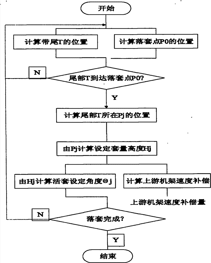
The invention relates to a stable sleeve-dropping method for a moveable sleeve of a hot milling machine and belongs to the technical field of steel rolling. According to the method, a sleeve-dropping controller controls a sleeve-dropping process of a rear moveable sleeve according to the following steps: tracking the position of a strip steel tail; confirming a sleeve-dropping position; establishing a sleeve-dropping angle control function; and lastly, after detecting and confirming that the strip steel tail reaches the confirmed sleeve-dropping position, starting a moveable sleeve rod and simultaneously controlling a sleeve-dropping angle of the moveable sleeve rod according to the sleeve-dropping angle control function till the moveable sleeve drops to the position as high as a rolling level. According to the method, by organically considering a frame driving transmission speed together with the moveable sleeve motion control, in the process of slowly digesting the sleeve quantity, a moveable sleeve roller keeps a tensile force on the strip steel till the moveable sleeve completely drops off, and the drifting phenomenon in a throwing process is prevented while a hollow sleeve isprevented from being formed, thereby achieving the purpose of stably dropping the sleeve.

Description

technical field [0001] The invention relates to a method for smoothly dropping a looper of a hot rolling mill, in particular to a method suitable for the smooth falling of a looper of a hot rolling mill, and belongs to the technical field of steel rolling. Background technique [0002] In the hot rolling production process, the strip needs to keep the "metal second flow rate" equal in each continuous rolling unit, and at the same time maintain a constant tension of the strip, which is mainly realized by the looper arranged between the continuous rolling units. [0003] The looper goes through three stages of looping, torque control and looping in each rolling cycle. In the ready state, the looper is located at the same height as the rolling horizontal line, that is, the looper roller at the end of the looper rod is located at a position tangent to the rolling horizontal line, so that the belt can be threaded smoothly. After the belt is threaded, the downstream frame bites t...

Claims


Application Information

Patent Timeline
Patent Type & Authority Patents(China)
IPC IPC(8): B21B41/00B21B41/12
Inventor 谢向群刘小光
Owner SHANGHAI MEISHAN IRON & STEEL CO LTD
Learn More