Eureka AIR delivers breakthrough ideas for toughest innovation challenges, trusted by R&D personnel around the world.

Horizontal gas separation device

A gas and horizontal technology, applied in the field of horizontal gas partition devices, can solve the problems of low safety performance, friction of sealing surfaces, complicated operation, etc., and achieve the effects of prolonging service life, good sealing performance and ensuring reliability.

Inactive Publication Date: 2011-10-05
吉卫星
View PDF5 Cites 0 Cited by
  • Summary
  • Abstract
  • Description
  • Claims
  • Application Information

AI Technical Summary

Problems solved by technology

Butterfly valve plus U-shaped pipe water seal structure device is a simple water seal device, which has single function, low safety performance, relatively large structure, and cumbersome operation; butterfly valve plus plate valve, glasses valve and other structural devices, although the structure is compact, the operation is also difficult. Convenient, but the sealing surface is easy to cause friction during operation, which will affect the service life and sealing performance of the device, and this structural device is difficult to use under the condition of large back pressure

Method used


Image

  • Horizontal gas separation device
  • Horizontal gas separation device
  • Horizontal gas separation device

Examples


Embodiment 1

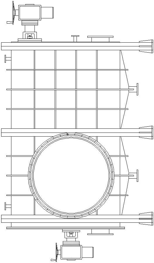
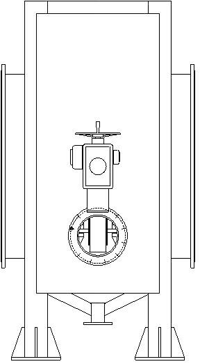
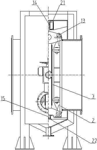
[0018] see figure 1 , figure 2 as well as image 3 and Figure 4 As shown, the present invention includes: a valve body 1, which is respectively provided with an inlet and an outlet, and the inlet and outlet are respectively used for connecting pipelines for conveying medium. A valve rod 10 is arranged in the valve body, and the valve rod is connected to the central support of the valve core. The spool center support includes: a support body 3, the upper part of which is connected to the valve stem nut 9, the valve stem nut is threadedly connected to the valve stem, and the support body is a frame for connecting the valve stem and the gate. The valve stem adopts multi-thread threads, that is, the valve stem is a double-headed trapezoidal screw, which makes the opening and closing of the center support frame of the valve core quick and the number of turns of the valve stem is small. The sealing surface provided on the inlet and outlet valve bodies is a layer of stainless s...

Embodiment 2

[0026] The invention comprises: a valve body, an inlet and an outlet are arranged on the valve body, and the inlet and the outlet are respectively used for connecting pipelines for conveying medium. A valve rod is arranged in the valve body, and the valve rod is movably connected with the center bracket of the valve core. The spool center support includes: a support body 3, the upper part of the support body is connected to the valve stem nut 9, and the valve stem nut is threadedly connected to the valve stem. The center support of the spool moves horizontally under the drive of the valve stem. The support body of the spool center bracket is provided with a strut, the strut is threadedly connected with a strut slider, the strut slider is hinged with a connecting rod, and one end of the strut is connected with a half coupling, corresponding to the position of the strut. The valve body is provided with a strut shaft, and one end of the strut shaft is connected with another half...

Embodiment 3

[0032] The invention comprises: a valve body, on which an inlet and an outlet are arranged, and a valve rod is arranged in the valve body, and the valve rod is movably connected with the center bracket of the valve core. The spool center support includes: a support body 3, the upper part of the support body is connected to the valve stem nut 9, and the valve stem nut is threadedly connected to the valve stem. The center support of the spool moves horizontally under the drive of the valve stem. There is a strut on the central support of the valve core, a strut slider is set on the strut, a connecting rod is hinged on the strut slider, one end of the strut is connected with a half coupling, and a valve body corresponding to the position of the strut is provided with There is a pole shaft, and one end of the pole shaft is connected to another half coupling, and the half coupling connected to the pole and the half coupling connected to the pole shaft form a complete jaw coupling t...


PUM


Abstract

The invention relates to a block valve on a gas transmission pipeline, in particular to a horizontal gas separation water seal device. The device comprises a valve body, wherein an inlet and an outlet are formed on the valve body respectively; a valve rod is arranged inside the valve body and is connected with a valve core center bracket; a supporting rod is arranged on the valve core center bracket and is in threaded connection with a supporting rod slide block; a connecting rod is hinged to the supporting rod slide block; one end of the supporting rod is connected with a half-coupling; a supporting rod rotating shaft is arranged on the valve body opposite to the supporting rod; one end of the supporting rod rotating shaft is connected with another half-coupling; the half-coupling connected with the supporting rod is matched with the half-coupling connected with the supporting rod rotating shaft; the connecting rod is hinged with a gate; and a sealing ring is arranged on the gate. Friction between the sealing ring and a sealing surface of the valve body is avoided, and the service life of the sealing ring is prolonged to the greatest degree.

Description

technical field [0001] The invention relates to a cut-off valve on a gas delivery pipeline, in particular to a horizontal gas cut-off device. Background technique [0002] At present, the pipeline cutting devices for conveying gas in metallurgical production mainly include butterfly valve plus U-shaped pipe water seal structure device, butterfly valve plus plug-in valve, glasses valve and so on. Butterfly valve plus U-shaped pipe water seal structure device is a simple water seal device, which has single function, low safety performance, relatively large structure, and cumbersome operation; butterfly valve plus plate valve, glasses valve and other structural devices, although the structure is compact, the operation is also difficult. It is convenient, but the sealing surface is easy to cause friction during operation, which will affect the service life and sealing performance of the device, and this structural device is difficult to use under the condition of large back pres...

Claims


Application Information

Patent Timeline
Patent Type & Authority Applications(China)
IPC IPC(8): F16K3/312F16K3/18
Inventor 吉卫星孙明亮
Owner 吉卫星
Why Eureka
Eureka Blog
Learn More