Motorized valve

An electric valve and valve stem technology, which is applied to lift valves, valve devices, valve details, etc., can solve the problems of a large number of parts and troublesome manufacturing, and achieve the effect of simplifying the manufacturing process, low manufacturing cost, and reducing manufacturing cost.

Active Publication Date: 2011-10-05
FUJIKOKI MFG CO LTD
View PDF5 Cites 27 Cited by
  • Summary
  • Abstract
  • Description
  • Claims
  • Application Information

AI Technical Summary

Problems solved by technology

[0008] However, in the above-mentioned conventional electric valve 51, when the driving mechanism 59 is configured, the stop ring 60 and the rotor 56 are integrally formed by insert molding, and the protrusion 61a on the upper part of the stem frame 61 is fitted into the stop ring 60. The inner peripheral hole is riveted to fix t...

Method used


Image

  • Motorized valve
  • Motorized valve
  • Motorized valve

Examples


Embodiment Construction

[0065] Hereinafter, embodiments of the present invention will be described in detail with reference to the drawings.

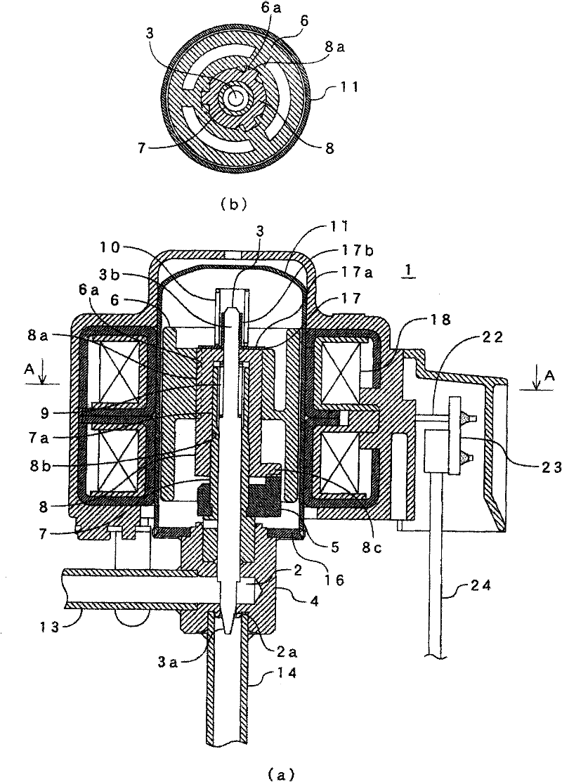
[0066] figure 1 Representing the first embodiment of the electric valve of the present invention, the electric valve 1 is composed of the following components: a valve body 4 having a valve chamber 2 and a valve hole 2a formed in the valve chamber 2; a valve core 3a, the The valve core 3a is formed at the lower end of the valve stem 3, and opens and closes the valve hole 2a; the casing 11 protruding from the valve body 4; the stator coil 18 arranged outside the casing 11; the stator coil 18 is energized and excited to rotate The rotor 6; the threaded pipe 7 fixed to the valve main body 4; the valve stem frame 8, which is formed to be able to rotate together with the rotor 6, and the valve core 3a passes through the threaded pipe 7 by the screw feed action The valve stem 3 lifts; the valve closing spring 9, which is assembled between the valve stem frame 8 an...


PUM


Abstract

The invention provides a motorized valve with a low manufacturing cost due to part number decrease and manufacturing process simplification. The motorized valve comprises a valve main body having a valve chamber and a valve hole formed in the valve chamber, a valve core for opening and closing the valve hole; a housing projecting from the valve main body; a stator coil equipped on the outer side of the housing; a resin rotor equipped on the inner side of the housing and performing rotation by means of the electrified excitation of the stator coil; a threaded pipe fixed on the valve main body; a resin valve rod frame configured in a way to rotate simultaneously with the rotor and making the valve core open and close the valve hole through a valve rod by means of the thread feeding motion between the valve rod frame and the threaded pipe; a valve-closing spring equipped between the valve rod frame and the valve rod and exerting force on the valve core through the valve rod towards the valve hole closing direction; and a limiter cooperating with the valve-closing spring for preventing relative motion of the valve rod frame and the rotor on the direction where the valve core opens and closes the valve hole.

Description

technical field [0001] The invention relates to an electric valve used for refrigerant flow control in a refrigeration cycle system. Background technique [0002] As an example of the above electric valve, such as image 3 As shown, the electric valve described in Patent Document 1 and the like includes: a valve body 54 having a valve chamber 52 and a valve hole 52a formed in the valve chamber 52; and a valve element 53 for opening and closing the valve hole 52a. The drive mechanism 59 inside the casing 57 protruding upward from the valve main body 54 drives the valve element 53 in the vertical direction to control fluid such as refrigerant. [0003] The driving of the spool 53 by the drive mechanism 59 is performed by a stepping motor composed of a rotor 56 provided inside the housing 57 and a stator 58 fitted outside the housing 57 . When the rotor 56 rotates, the stop ring 60 and the stem frame 61 rotate accordingly, and the valve core 53 is raised and lowered to open an...

Claims


Application Information

Patent Timeline
IPC IPC(8): F16K31/06F16K1/32F16K1/02F25B41/06
Inventor 小柳津薰大内共存梅泽仁志
Owner FUJIKOKI MFG CO LTD
Why Eureka
Try Eureka