Automatic temperature control gas cooker and temperature control method

A technology for gas stoves and cooktops, which is applied in the field of gas stoves, can solve the problems of transmission, easy failure, poor thermal conductivity, etc., and achieves the effects of accurate measurement and easy realization.

Active Publication Date: 2013-07-31
叶小舟 +1
View PDF4 Cites 0 Cited by
  • Summary
  • Abstract
  • Description
  • Claims
  • Application Information

AI Technical Summary

Problems solved by technology

[0004] Its disadvantages are: due to the contact heat conduction, and there is usually dirt on the bottom of the pot, which affects the joint of the contact surface, the thermal conductivity is poor. In full contact with the bottom of the pot, it is difficult to ensure that the temperature at the bottom of the pot is accurately and timely transmitted to the temperature limiter, and the temperature around the temperature limiter will be very high due to the combustion of the burner, which often affects the temperature of the temperature limiter. The temperature in the pot is inconsistent, and because the temperature limiter is demagnetized at the Curie point, the existing technology can only control the temperature of one point, and it is difficult to detect multiple temperature points, because different cooking procedures require different temperature points to be controlled , that is, not all cooking procedures are required to reach the Curie point to work, and this detection method can only detect the temperature of the Curie point of the temperature limiter, but not the temperature of multiple points, so it cannot be used in the cooking process of the gas stove. Flexible and accurate control of multi-point temperature, temperature detection is still limited
[0005] How to achieve a wider temperature range and continuous non-contact temperature control, and explain it from the principle and mechanism, the prior art does not give any inspiration, in view of this, the present invention is proposed

Method used


Image

  • Automatic temperature control gas cooker and temperature control method
  • Automatic temperature control gas cooker and temperature control method
  • Automatic temperature control gas cooker and temperature control method

Examples


Embodiment Construction

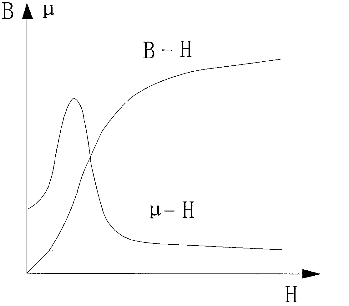
[0039] The invention utilizes the magnetic permeability temperature characteristic of the iron or ferrimagnet to realize the non-contact temperature measurement method of the gas cooker. The magnetic permeability (or magnetic induction, magnetization) of ferromagnets, ferrimagnets or ferrites has a very complicated relationship with temperature and other parameters. They are affected by factors such as frequency, temperature, and magnetic property transformation before and after the Curie point. For details, please refer to the disclosure content cited below.

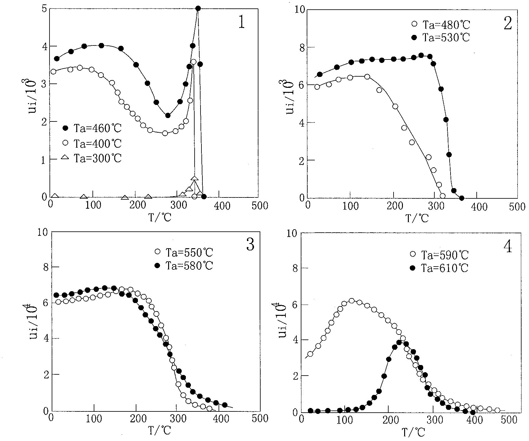
[0040] "Functional Materials" Supplement 2001 No. 10 published a "Fe 83 Nb 6 B 11 Alloy Magnetic Permeability Changes with Temperature", from which it can be seen that the alloy magnetic permeability has a complex relationship with temperature, and even, under different conditions, their relationship coefficients have completely different trends , see attached figure 1 .

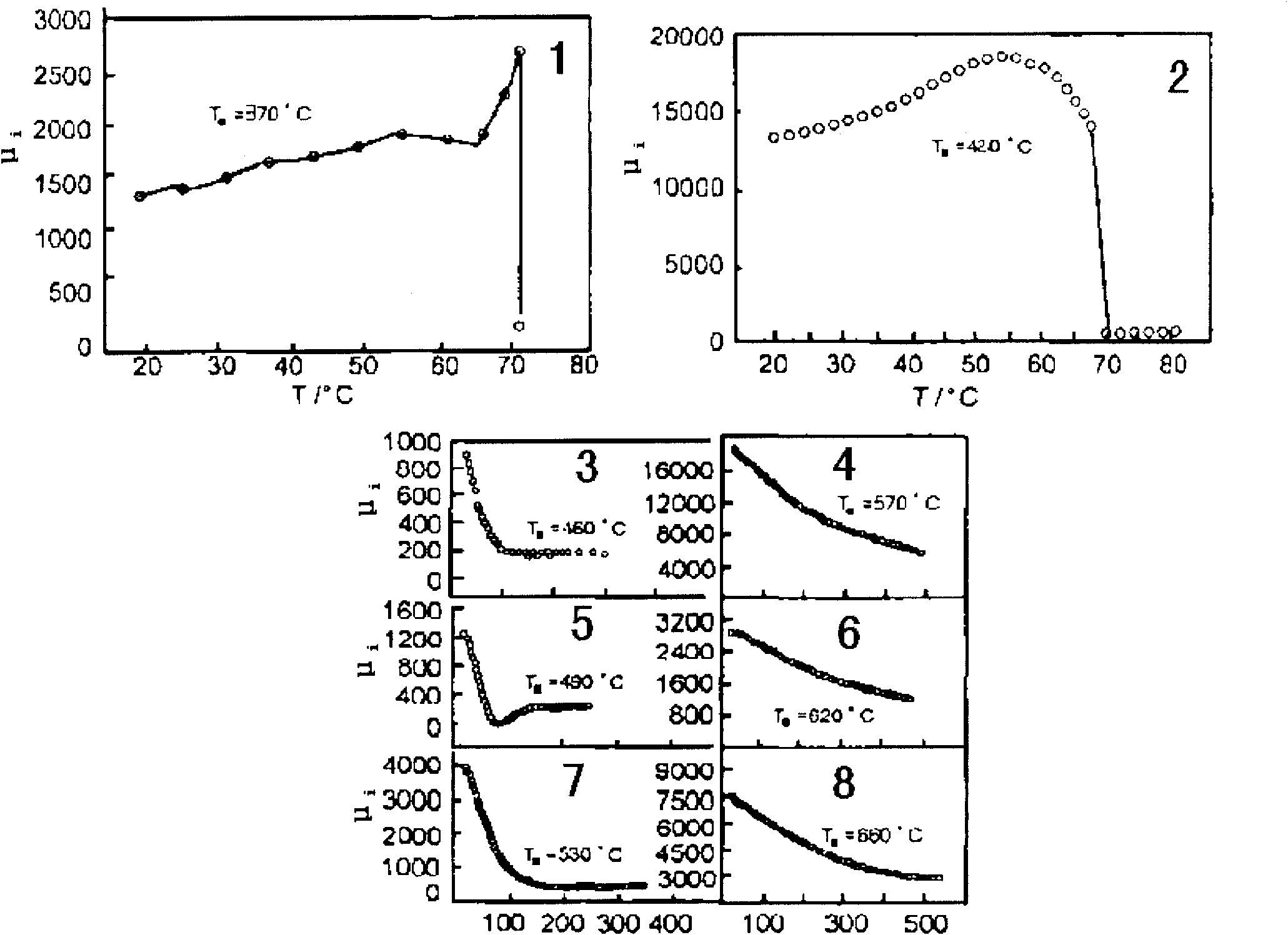
[0041] "Relationship between magnetic perm...


PUM


Abstract

The invention discloses an automatic temperature control gas cooker and a temperature control method. The gas cooker comprises a cooking bench seat, a combustor, a support foot frame and a cooking pan, wherein the combustor is arranged on the cooking bench seat; the cooking pan is arranged on the support food frame; a temperature measuring element is arranged at the center of the combustor and comprises a temperature measuring induction coil and a magnet exciting coil; the bottom part of the cooking pan is provided with a magnetic temperature-sensing element of which magnetic induction intensity corresponding to the magnet exciting coil changes with temperature; the temperature measuring induction coil is excited by the magnet exciting coil, a temperature-sensing detection magnetic field is formed between the temperature measuring induction coil and the magnetic temperature-sensing element and is used for converting magnetic signals generated by the magnetic temperature-sensing element at different temperatures into electric signals and outputting the electric signals to detect the temperature of the cooking pan. By the gas cooker provided by the invention, continuous non-contact-type temperature measuring within a working range is realized, and the adaptation range of the gas cooker in the working process is widened maximally.

Description

technical field [0001] The invention relates to a gas cooker, in particular to a gas cooker and a temperature control method for realizing non-contact temperature measurement and automatic temperature control by utilizing the magnetic permeability temperature characteristics of iron or ferrous magnets. Background technique [0002] Gas stoves refer to kitchen utensils that are heated directly by gaseous fuels such as liquefied petroleum gas, artificial gas, and natural gas. When the ignition switch is turned on, the current released from the battery is transformed by a transformer (electronic pulse electric fire), and the voltage is very high (up to 20,000 volts). When it breaks through the air, an electronic pulse spark is generated. After the ignition switch is turned on, the gas also passes through the pipe to the nozzle, and after reaching the nozzle, it burns rapidly due to the spark of the electronic ignition. At this time, even if the knob is loosened to stop the igni...

Claims


Application Information

Patent Timeline
Patent Type & Authority Patents(China)
IPC IPC(8): F24C3/08F24C3/12
Inventor 叶小舟彭霭钳刘劲旋林卫文武炜
Owner 叶小舟
Why Eureka
Try Eureka