A non-contact temperature measurement method and a device using the temperature measurement method

A non-contact, temperature-sensing technology, used in measuring devices, thermometers using electrical devices, and thermometers that are directly sensitive to heat

Inactive Publication Date: 2014-10-15
叶小舟
View PDF8 Cites 4 Cited by
  • Summary
  • Abstract
  • Description
  • Claims
  • Application Information

AI Technical Summary

Problems solved by technology

[0007] Its disadvantages are: due to the contact heat conduction, and there is usually dirt on the bottom of the pot, which affects the joint of the contact surface, the thermal conductivity is poor. In full contact with the bottom of the pot, it is difficult to ensure that the temperature at the bottom of the pot is accurately and timely transmitted to the temperature limiter, and the temperature around the temperature limiter will be very high due to the combustion of the burner, which often affects the temperature of the temperature limiter. The temperature in the pot is inconsistent, and because the temperature limiter is demagnetized at the Curie point, the existing technology can only control the temperature of one point, and it is difficult to detect multiple temperature points, because different cooking procedures require different temperature points to be controlled , that is, not all cooking procedures are required to reach the Curie point to work, and this detection method can only detect the temperature of the Curie point of the temperature limiter, but not the temperature of multiple points, so it cannot be used in the cooking process of the gas stove. Flexible and accurate control of multi-point temperature, temperature detection is still limited
Its disadvantage is: due to the existence of strong electromagnetic field when the microwave oven is working, when the microwave oven is working, its strong magnetic field will interfere with the magnetic sensor's detection of the magnetic signal sent by the temperature-sensitive magnetic steel at the set temperature point. Therefore, let the magnetic sensor detect when the magnetron is powered off. After the detection work is completed, the magnetron is powered on again. This process continues until the magnetic sensor detects that the food is at a certain set temperature. until the signal
Therefore, this technical solution has the following defects: (1) in order to ensure the normal detection of the magnetic sensor, the power supply of the magnetron should be often disconnected, which is not conducive to the normal heating work of the microwave oven; The power supply time of the electric tube will vary according to the amount of food to be heated. Therefore, it is difficult to set a more suitable time point for all situations. If the power-off time point is set early, the number of power-off times will increase and If the detection time is too long, it will affect the heating efficiency; (3) The frequent switching action of the high-power magnetron or power module of the microwave oven will have an impact on the control system, which will affect the service life of the control system; (4) It is difficult to control multiple temperatures Point detection: Since different cooking procedures require the control of different temperature points, that is, not all cooking procedures require reaching the Curie point to work, and this detection method can only detect the Curie point temperature of the temperature-sensing magnetic steel, and the It cannot detect multi-point temperature, so it cannot flexibly and accurately control the multi-point temperature required in the microwave cooking process, and the temperature detection is still limited
[0012] How to achieve a wider temperature range and continuous non-contact temperature control, and explain it from the principle and mechanism, the prior art does not give any inspiration, in view of this, the present invention is proposed

Method used


Image

  • A non-contact temperature measurement method and a device using the temperature measurement method
  • A non-contact temperature measurement method and a device using the temperature measurement method
  • A non-contact temperature measurement method and a device using the temperature measurement method

Examples


Embodiment 1

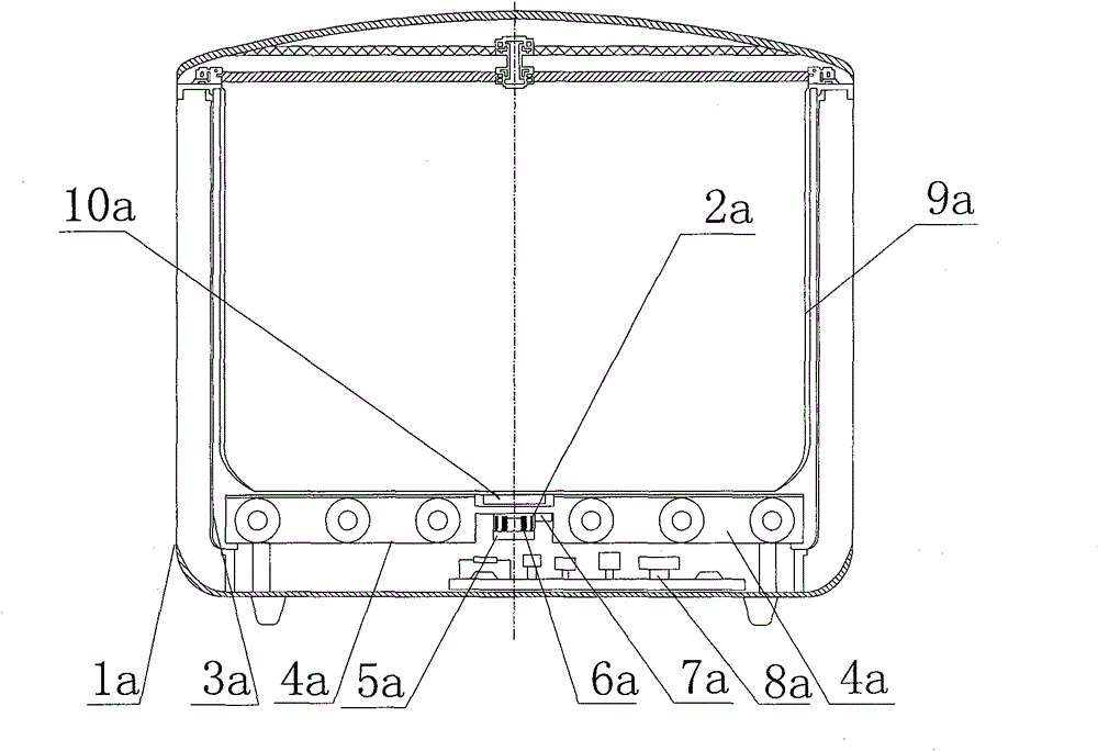
[0122] Such as Figure 13 , 14 As shown, the electric rice cooker described in this embodiment is an ordinary electric rice cooker. In the outer shell 1a of the electric rice cooker, an inner shell 3a, an inner pot 9a, and a heating plate 4a are included. The electric heating tube is embedded in the heating plate. A magnetic temperature-sensing element 10a that is always in contact with the inner pot 9a is arranged at the bottom, and a temperature-measuring induction coil 6a is arranged at the corresponding position of the magnetic temperature-sensing element 10a in the center of the heating plate 4a, which is called in this embodiment The temperature-measuring induction coil, an excitation coil 2a, and the corresponding control circuit 8a, the temperature-measuring induction coil and the thermistor 7a are fixed below the bottom of the inner shell 3a by the bracket 5a, and the magnetic temperature-sensing element 10a is centered and fixed on the inner shell 3a upper surface o...

Embodiment 2

[0128] The rice cooker in Embodiment 1 is an ordinary rice cooker, not an electromagnetic rice cooker. This embodiment is an electromagnetic rice cooker. The heating plate 4a is an electromagnetic heating coil, and the magnetic temperature sensing element 10a is installed at the bottom of the inner pot 9a and the bottom of the inner shell 3a. An excitation coil 2a is arranged on the surface, or the electromagnetic heating coil is used as the excitation coil at the same time, that is, the electromagnetic heating coil doubles as the magnetic temperature sensing element 10a and the temperature measuring device 10a while applying an alternating magnetic field to heat the inner pot made of ferromagnetic material. The excitation coil of the induction coil 6a, the inner pot 9a is made of ferromagnetic material, the size, shape and quality of the inner pot, the size, shape and quality of the magnetic temperature sensing element, and various parameters between the temperature measurement...

Embodiment 3

[0133] Others are the same as the second embodiment, the difference is that since the magnetic temperature sensing element 10a in the second embodiment is arranged in the middle of the heating plate 4a, in order to avoid or reduce the influence of the electromagnetic heating coil on the magnetic temperature sensing element 10a and the temperature sensing coil 6a A high-permeability ferromagnetic shielding ring can be arranged between the electromagnetic heating coil and the temperature-measuring induction coil 6a. At the same time, this method can also reduce the influence of the electromagnetic heating coil on the magnetic temperature-sensing element 10a. Specifically, methods of prior art can be used, for example: "Difficulties in electromagnetic shielding-magnetic field shielding" (Electronic Quality 2006 No. 10) discloses low-frequency magnetic fields (referring to alternating magnetic fields below 100 kHz, while household electromagnetic rice cookers The working frequency ...


PUM

PropertyMeasurementUnit
Curie pointaaaaaaaaaa

Abstract

The invention discloses a non-contact temperature measurement method and a device using the same. The device comprises a component needing temperature measurement, wherein at least one magnetic temperature sensing element and a temperature measurement element corresponding to the magnetic temperature sensing element are arranged at a contact part of the component needing temperature measurement; the temperature measurement element comprises a temperature measurement sensing coil and a magnet exciting coil, and further comprises a control circuit; the magnetic temperature sensing element is an iron magnet or a ferrous magnet; an alternating electric field is applied on the magnet exciting coil by using the temperature property of magnet permeability matched with the magnet exciting coil and the temperature measurement sensing coil; when the magnet exciting coil works, a basic electric signal is generated in the temperature measurement sensing coil, and excites the magnetic temperature sensing element simultaneously; when the temperature of an object to be measured is varied, the magnetic sensing intensity of the magnetic temperature sensing element is varied, and the electric signal of the corresponding temperature when the variation is reflected in the magnetic temperature sensing element; and the detection and control of the temperature are realized through the control circuit.

Description

technical field [0001] The invention relates to a temperature measuring method, in particular to a non-contact temperature measuring method and a device using the temperature measuring method by using the magnetic permeability temperature characteristics of iron or ferrous magnets. Background technique [0002] Usually, the oil temperature for frying food is about 160-170°C. If you want to deep-fry the food, the oil temperature is about 190°C. At 90-120°C, the bubbles disappear and the oil surface is calm; at 120-170°C, the oil temperature rises sharply, but the oil surface remains calm; at 170-210°C, there is a small amount of blue smoke and there are a few small ripples on the oil surface; once it reaches 210- At 250°C, a large amount of blue smoke containing acrolein will be formed, and various poisons such as thermal polymers of oil and polycyclic aromatic hydrocarbons will be produced. Therefore, temperature control in the process of cooking with oil is necessary. It is...

Claims


Application Information

Patent Timeline
Patent Type & Authority Patents(China)
IPC IPC(8): G01K7/38F24C3/12F24C7/08
Inventor 叶小舟彭霭钳刘劲旋林卫文武炜
Owner 叶小舟
Why Eureka
Try Eureka