
Image-method particle-size analyzer

A technology of particle analysis and image method, which is applied in the direction of particle and sedimentation analysis, particle size analysis, instruments, etc., can solve the problems of unsuitable particle analysis and large size, and achieve the effect of reducing size and being easy to carry

Inactive Publication Date: 2011-10-05
UNIV OF SHANGHAI FOR SCI & TECH
View PDF6 Cites 9 Cited by
  • Summary
  • Abstract
  • Description
  • Claims
  • Application Information

AI Technical Summary

Problems solved by technology

[0004]Because the image method particle size analyzer is improved from the traditional microscope, the structure of the traditional microscope makes the size of the image method particle size analyzer relatively large, which is suitable for analyzing particle samples in the laboratory , but not suitable for particle analysis in the field etc.

Method used


Image

  • Image-method particle-size analyzer
  • Image-method particle-size analyzer
  • Image-method particle-size analyzer

Examples


Embodiment 1

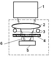
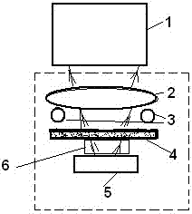
[0017] Depend on figure 1 As shown, an image-based particle analyzer is characterized in that, from top to bottom, the analyzer includes a digital camera 1, a microscope objective lens 2, a reflected light source 3, a transmitted light source 7, a sample cell 5 or a slide 4, and a microscopic The distance adjustment support frame 6 is composed of the microscopic objective lens 2, the reflection light source 3, the transmission light source 7, the sample pool 5 or the carrier film 4 and the macro distance adjustment support structure 6 into an integral part; the reflection light source 3, transmission light source 7 are all white light diodes.

[0018] During the transmission method measurement, the light that is positioned at the lowermost transmission light source light emitting diode 7 sends to illuminate the particle sample on the sample pool 5 or slide glass 4, and the particle image is enlarged and imaged on the image plane by the microscope objective lens 2, and the enla...

Embodiment 2

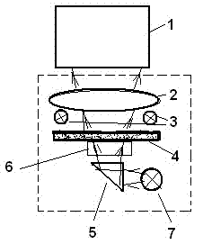
[0022] Considering the structural needs, a total reflection prism or mirror can be added between the sample cell or slide and the transmission light source, and the transmission light source is arranged at an angle of 90 degrees to the optical axis of the microscope objective lens, through the total reflection prism or Mirrors, etc. bend the light 90 degrees to illuminate the sample cell or the particle sample on the glass slide. The particle image is enlarged and imaged on the image plane by the microscope objective lens 2, and the image signal obtained after the enlarged image is received by the digital camera 1 is sent to a computer for image processing to obtain particle size distribution and shape factor parameters.


PUM


Abstract

The invention discloses an image-method particle-size analyzer, which has the characteristics that a digital camera, a micro-objective lens, reflection light sources, a sample cell or a glass slide, a microspur adjusting supporter and a transmission light source are sequentially arranged on the particle-size analyzer from the top down, wherein the reflection light sources and the transmission light source all adopt light-emitting diodes; the sample cell or the glass slide is arranged on the microspur adjusting supporter; when measurement is performed, a clear image can be obtained by adjusting the microspur adjusting supporter; if the transmission light source is lighted and the reflection light sources are not lighted, the transmission method is used for measurement; if the reflection light sources are lighted and the transmission light source is not lighted, the reflection method is used for measurement; and the micro-objective lens, a light-emiting light source and the sample cell constitute an integral component, and the integral component can be conveniently detachably connected with the digital camera to constitute the image-method particle-size analyzer. The invention has the beneficial effects that the size of the image-method particle-size analyzer can be greatly reduced by adopting the structure, and a protable minitype image-method particle-size analyzer with wide particle-size measurement range is constituted.

Description

technical field [0001] The invention relates to a measuring device for measuring and analyzing particle size and appearance by an image method, in particular to a replaceable particle size analyzer with an illumination light source and a microscopic objective lens of a sample pool. Background technique [0002] In recent years, with the development of CCD and CMOS digital cameras, image-based particle size analyzers that use digital cameras instead of eyepieces on traditional microscopes have been widely used. Image method particle size analyzers are divided into static image method particle size analyzers and dynamic image method particle size analyzers according to whether the measured particles are in a static state or a flowing state. The static image particle size analyzer is improved on the microscope. The original eyepiece on the microscope is replaced by a CCD or CMOS digital camera or a digital camera. The particle sample is placed on a glass slide. After the digita...

Claims


Application Information

Patent Timeline
Patent Type & Authority Applications(China)
IPC IPC(8): G01B11/24G01N15/02
Inventor 蔡小舒苏明旭
Owner UNIV OF SHANGHAI FOR SCI & TECH
Learn More