
Array antenna single-point mutual decoupling correction method

An array antenna and correction method technology, applied in diversity/multi-antenna systems, space transmit diversity, transmission monitoring, etc., can solve problems such as huge amount of computation, inability to guarantee unique identification of parameter estimation, and inability to guarantee global convergence of parameter estimation, etc. , to achieve the effect of small amount of calculation and reduce the amount of calculation

Active Publication Date: 2011-10-05
NO 54 INST OF CHINA ELECTRONICS SCI & TECH GRP
View PDF3 Cites 10 Cited by
  • Summary
  • Abstract
  • Description
  • Claims
  • Application Information

AI Technical Summary

Problems solved by technology

Self-calibration does not require auxiliary sources with known orientation, but due to the coupling between error parameters and orientation parameters and some ill-conditioned array antenna structures (such as uniform linear arrays), the unique identification of parameter estimation is often not guaranteed, and The high-dimensional, multi-mode nonlinear optimization problem corresponding to the joint estimation of parameters brings a huge amount of calculation, and the global convergence of parameter estimation is often not guaranteed

Method used


Image

  • Array antenna single-point mutual decoupling correction method
  • Array antenna single-point mutual decoupling correction method

Examples


Embodiment Construction

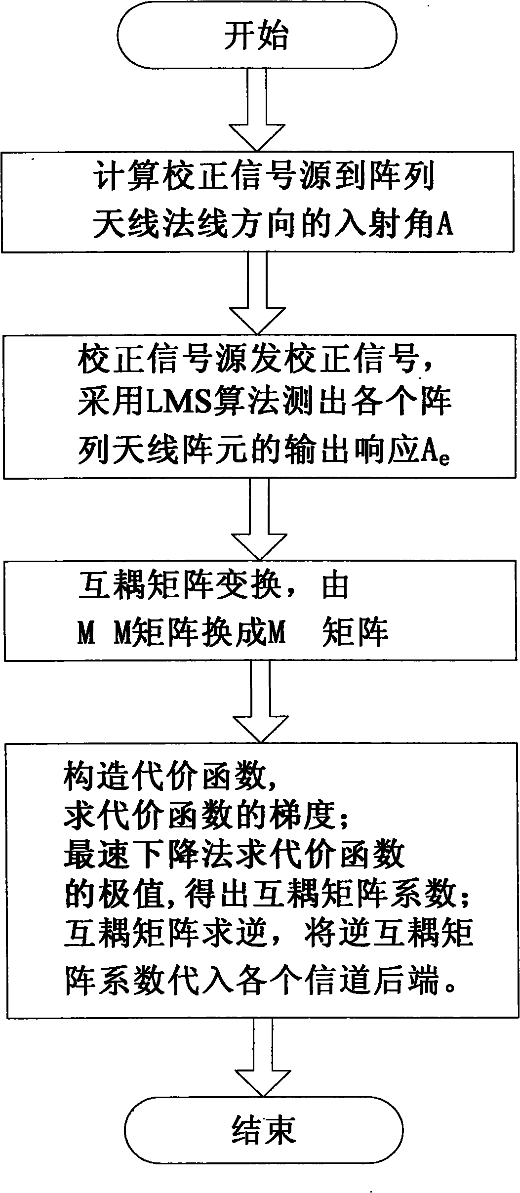
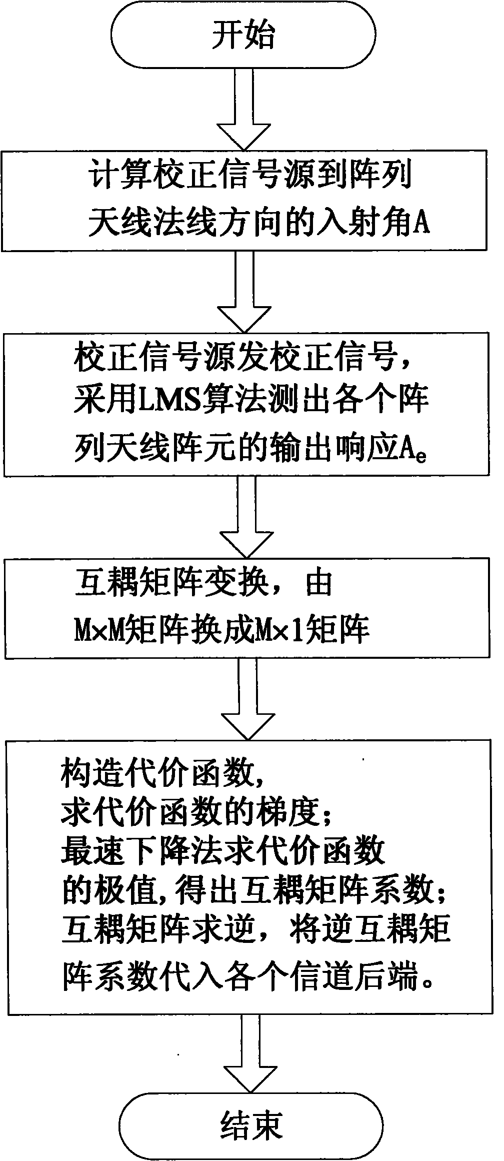
[0017] refer to figure 1 , the present invention only adopts single-point correction, transmits the correction signal at any point in any direction of the far field of the array antenna, measures the incident direction of the correction signal to the normal line of the array antenna, and calculates the direction of the correction signal to each array element of the array antenna Vector A (indicated by the letter A); the correction signal source transmits the correction signal, and uses the LMS (least mean square) algorithm to measure the amplitude and phase errors of the output signals of other array antenna elements relative to the first array antenna element, and obtain Mutual coupling error direction vector A e (with the letter A e express); transform and simplify the mutual coupling matrix Γ (represented by the letter Γ); construct a cost function, find the minimum value of the cost function, and obtain the mutual coupling matrix; finally invert the mutual coupling matrix...


PUM


Abstract

The invention discloses an array antenna single-point mutual decoupling correction method, which relates to a large array antenna mutual coupling correction technology and is particularly applied to a one-dimensional uniform linear array and a uniform round array. The method comprises the following steps of: arranging a correction signal source for transmitting signals at any direction in a far field, and measuring an incident angle of the correction signal source to a normal direction of an antenna array; transmitting the signal by using the correction signal source, and measuring the output response of each antenna array element; performing simplified transform on a mutual coupling matrix; constructing a cost function, calculating an extremum of the cost function, and obtaining a mutual coupling matrix coefficient; and inversing the mutual coupling matrix, and substituting an inverse matrix coefficient of the mutual coupling matrix into each channel, thereby realizing array antenna single-point mutual decoupling correction. The method has the advantages that: the method is simply implemented, convenient to operate, low in calculated amount and particularly applied to the large array antenna mutual coupling correction of the one-dimensional uniform linear array and the uniform round array; and only the single point response of the antenna array in any direction is required to be measured, and the measurement of the whole directional diagram of an array antenna is not required.

Description

technical field [0001] The invention relates to a method for mutual coupling correction of large array antennas, and is especially suitable for one-dimensional uniform linear arrays and uniform circular arrays. Background technique [0002] The traditional mutual coupling correction method of array antennas generally first conducts electromagnetic measurement of mutual coupling or analyzes and calculates the mutual coupling effect through electromagnetic calculation methods, and then uses the measured or calculated values ​​of mutual coupling to correct the subsequent signal processing algorithm. However, the accuracy of the electromagnetic measurement and calculation values ​​of the mutual coupling often cannot meet the actual engineering application; moreover, the mutual coupling of the array element will also change with the environment and the electromagnetic parameters of the array element. The measured and calculated values ​​of the coupling are constantly corrected. ...

Claims


Application Information

Patent Timeline
IPC IPC(8): H04B7/04H04B17/00H04B17/12
Inventor 桑士伟崔焱郗洪杰贾立哲高杰罗枫
Owner NO 54 INST OF CHINA ELECTRONICS SCI & TECH GRP
Learn More