
Reinforcing

A technology of reinforcing ribs and steel bars, which is applied in the direction of building reinforcements, key connections, rod connections, etc., can solve problems such as increased corrosion, excessive longitudinal slip, cracking, etc., and achieve the effect of reducing constraints

Inactive Publication Date: 2011-10-05
MB连接件有限公司
View PDF6 Cites 18 Cited by
  • Summary
  • Abstract
  • Description
  • Claims
  • Application Information

AI Technical Summary

Problems solved by technology

If these properties are not within a certain tolerance range, the joint structure will obviously affect the final structure, for example, if the longitudinal slip is too large, it will cause local cracking and increase the risk of corrosion, and may cause excessive deformation.
If the major parts of the connecting structure and reinforcement are not flexible enough, local stress concentrations will be induced which can lead to severe failure of the connection
[0007]The use of separate connectors, such as the above-mentioned threaded sleeves, creates the risk of a mismatch between the reinforcing bars and the sleeves where there are steel bars of different strengths at the site, and , the use of a sleeve structure requires a large space between components for easy installation, which in turn leads to excessive longitudinal slippage under load
And there is also a constant risk that the connection is not sufficiently secured in place, which will break the connection

Method used


Image

  • Reinforcing
  • Reinforcing
  • Reinforcing

Examples


Embodiment Construction

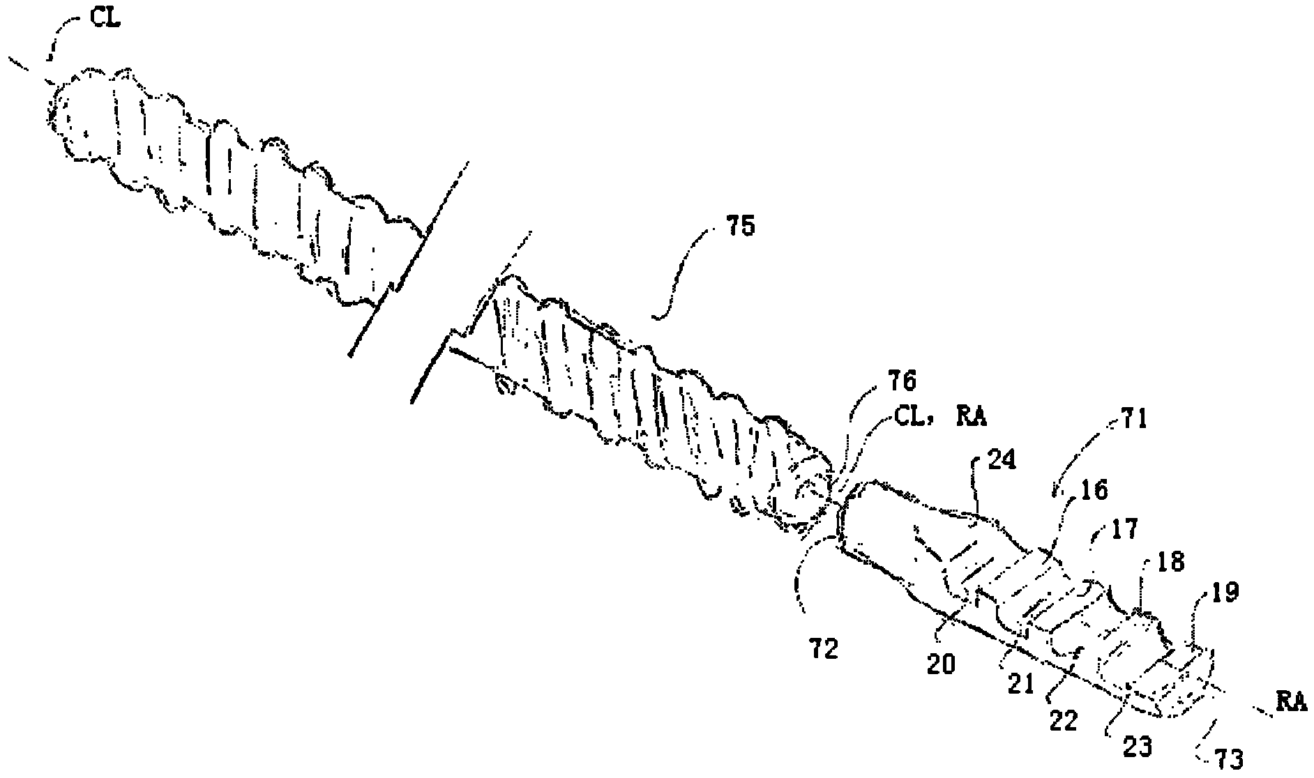
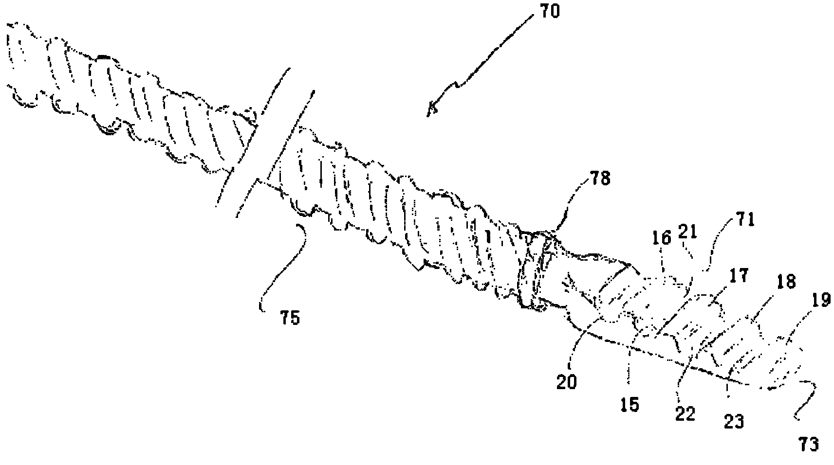
[0055] first as Figures 1 to 3 As shown in the partial view of the reinforcing bar 10 , the reinforcing bar 10 generally made of steel includes an axis 11 extending along the length of the reinforcing bar 10 . Only a small part of the shaft 11 is shown, it being noted that the shaft can extend for several meters. Rebar is manufactured in continuous lengths and cut to different sizes according to specific needs. Furthermore, the shaft 11 is shown as flat for convenience. It is worth noting that the shaft can contain threads, such bars are often referred to as deformed bars.

[0056] The bar 10 also includes a terminating structure 12 extending along the end of the bar to an end 13 of the bar 10, the terminating structure 12 is shown integral with the axis 11 and enlarged compared to the axis 11 (i.e. it is defined by the central axis of the bar). The distance extending radially outward is greater than the distance extending outward of the shaft 11 ), and a transition zone 1...


PUM


Abstract

Reinforcing is disclosed that comprising a reinforcing bar extending along a portion of the length of the reinforcing and a termination extending along an end portion of the reinforcing. The termination is disclosed as being permanently bonded to the reinforcing bar preferably by a friction welding process so as to form an integral connection. The termination has a body extending in a longitudinal direction between opposite first and second ends, and a lateral engagement face formed on the body. In use the first end is joined to an end the reinforcing bar, and the engagement face incorporates locking formations thereon arranged to interfit with a complementary shaped termination to form an interlock arranged to accommodate loading applied in the longitudinal direction.

Description

technical field [0001] The present invention generally relates to reinforcing bars of concrete or other cementitious structures, and more particularly to connections between reinforcing bars as described above and below. However, it is worth noting that the present invention has a wide range of applications and can be applied to the connection of steel bars and other rigid objects such as iron plates and the like. Background technique [0002] In construction, concrete structures (such as walls, floors, slabs, and columns) are structures formed by placing reinforcing bars, such as steel bars, in an area followed by pouring concrete therein. These bars are supported in predetermined locations and it is often necessary to connect multiple bars to each other to ensure that the reinforcement not only sits properly but also transfers the load through the connection so that the bars are in tension or compression over most or even their entire length . [0003] In the past, metal...

Claims


Application Information

Patent Timeline
IPC IPC(8): E04C5/01E04C5/16F16B3/00B21C37/04E04C5/18F16B7/00C21D8/08F16B1/00F16B7/22
CPCC21D9/50C21D7/105E04C5/165B21F15/08B21C37/04E04C5/01E04C5/16F16B3/00
Inventor 欧内斯特·科默福德
Owner MB连接件有限公司
Learn More