Eureka AIR delivers breakthrough ideas for toughest innovation challenges, trusted by R&D personnel around the world.

Polarization aligned and polarization graded thermoelectric materials and method of forming thereof

A technology of thermoelectric materials and polarization fields, which can be applied to thermoelectric device node lead-out materials, circuits, and thermoelectric devices that only use the Peltier or Seebeck effect, etc., and can solve the problem of no substantial increase in ZT

Inactive Publication Date: 2011-10-05
CARRIER CORP
View PDF0 Cites 4 Cited by
  • Summary
  • Abstract
  • Description
  • Claims
  • Application Information

AI Technical Summary

Problems solved by technology

These offset changes usually result in ZT no real increase

Method used


Image

  • Polarization aligned and polarization graded thermoelectric materials and method of forming thereof
  • Polarization aligned and polarization graded thermoelectric materials and method of forming thereof
  • Polarization aligned and polarization graded thermoelectric materials and method of forming thereof

Examples


Embodiment Construction

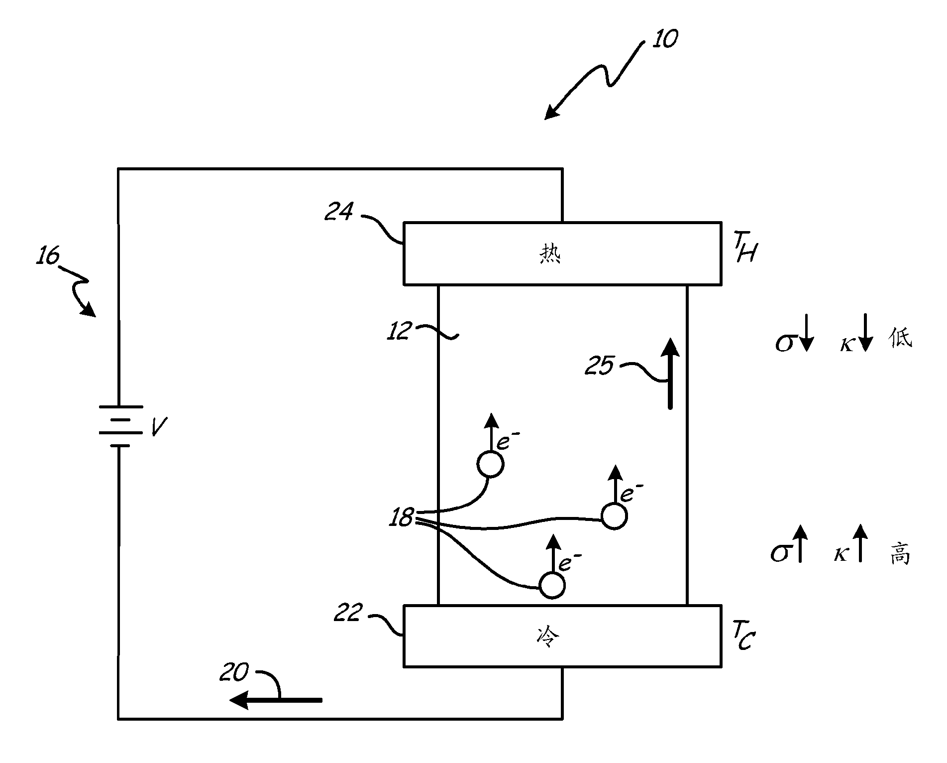
[0025] figure 1 A simplified schematic diagram of a thermoelectric cooling device 10 utilizing the Peltier effect in a thermoelectric material 12 to convert electrical energy into a thermal gradient ΔΤ is depicted. When an input voltage V is applied to circuit 16 , electrons 18 flow in material 12 , resulting in a current I in the direction indicated by arrow 20 . As electrons 18 pass through material 12, a thermal gradient ΔT=T is created due to heat Q flowing away from cold side 22 towards hot side 24 as indicated by arrow 25 H -T C . A thermal gradient ΔT is maintained by the current 20 across the material 12 as heat is removed from the hot side 24 via heat removal means such as a heat sink or heat exchanger (not shown), thereby inducing a continuous The temperature decreases until an equilibrium state is reached. The thermal gradient ΔT arises from the relative electrical and thermal energy flow due to the conductivity of charge carriers and acoustic phonons through t...


PUM


Abstract

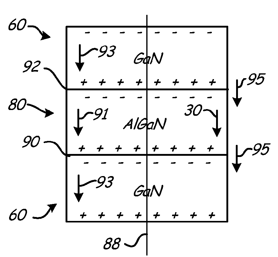
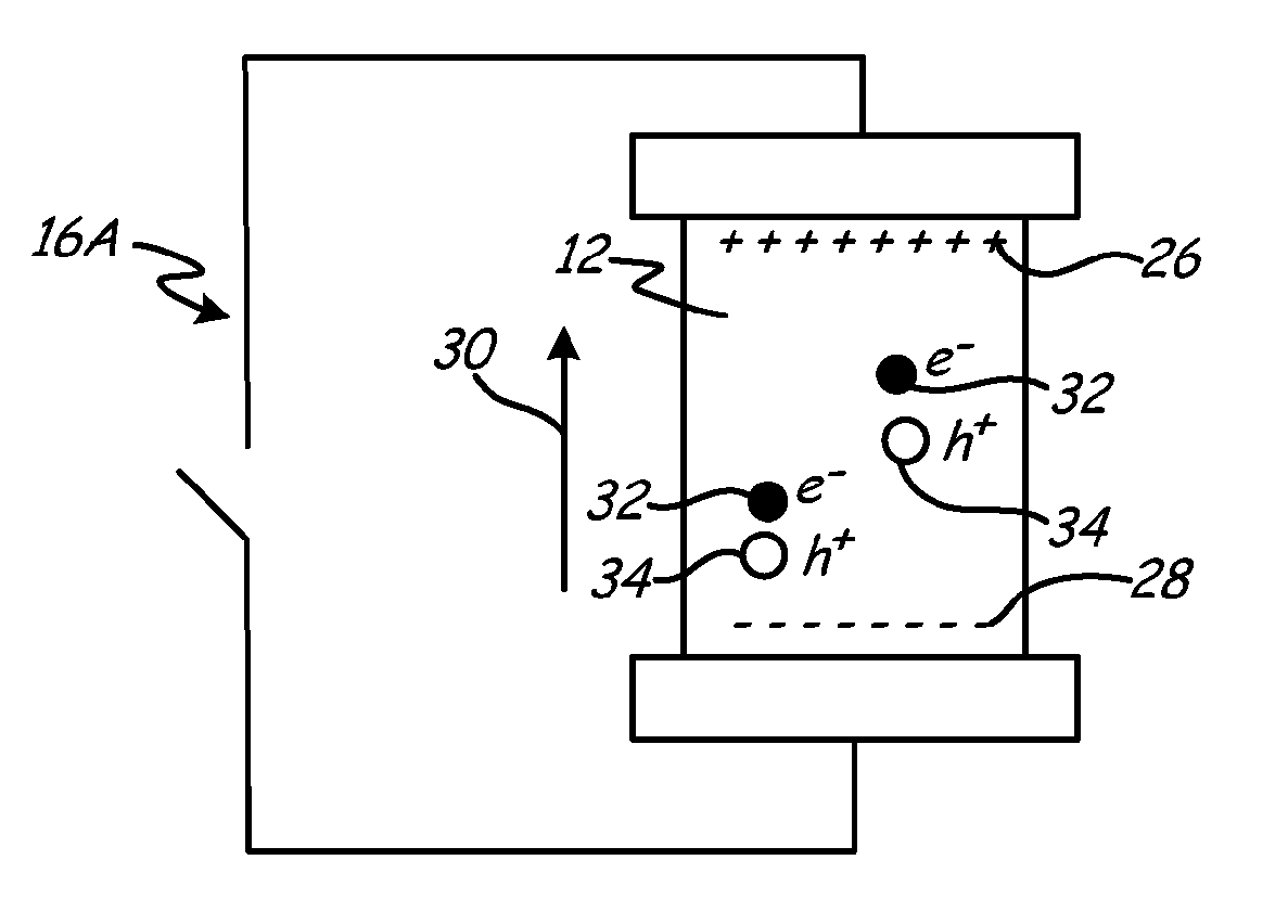
Exemplary embodiments of the invention include a thermoelectric material having an aligned polarization field along a central axis of the material. Along the axis are a first atomic plane and a second atomic plane of substantially similar area. The planes define a first volume and form a single anisotropic crystal. The first volume has a first outer surface and a second outer surface opposite the first outer surface, with the outer surfaces defining the central axis passing through a bulk. The bulk polarization field is formed from a first electrical sheet charge and a second opposing electrical sheet charge, one on each atomic plane. The opposing sheet charges define a bulk polarization field aligned with the central axis, and the bulk polarization field causes asymmetric thermal and electrical conductivity through the first volume along the central axis.

Description

Background technique [0001] Thermoelectric materials exhibit a predictable relationship between their electrical and thermal properties. Thermoelectric devices are often arranged as either cooling / heat pump devices or generators, depending on the desired result. To use a material as a cooling device or heat pump, an electric field is typically applied across the material via an electrical circuit. As long as the field is maintained, the field produces a thermal gradient according to the Peltier effect. Heat may be removed from the hot side of the material by heat sinks, heat exchangers or other heat removal means. When both are done simultaneously, the device effectively operates as a chiller or heat pump. In contrast, creating a thermal gradient across the material, such as by applying thermal energy, induces an electric field according to the Seebeck effect. Connecting the material to an electrical circuit aligned with this field results in the device effectively operati...

Claims


Application Information

Patent Timeline
Patent Type & Authority Applications(China)
IPC IPC(8): H01L35/32H01L35/28H10N10/10H10N10/17H10N10/852H10N10/01H10N10/853H10N10/855H10N10/857
CPCH01L21/02568H01L35/26H01L21/0254H01L35/22H01L21/02458H10N10/857H10N10/855
Inventor J.曼特斯
Owner CARRIER CORP
Why Eureka
Eureka Blog
Learn More