Time interpolation flash adc having automatic feedback calibration

An analog-to-digital converter and flash technology, applied in the direction of analog-to-digital converter, analog/digital conversion, code conversion, etc., can solve problems such as distortion and noise

Inactive Publication Date: 2011-10-05
NXP BV
View PDF4 Cites 10 Cited by
  • Summary
  • Abstract
  • Description
  • Claims
  • Application Information

AI Technical Summary

Problems solved by technology

Distortion and noise introduced by the extended "hold" time of the internal sample-and-hold circuit is another concern

Method used


Image

  • Time interpolation flash adc having automatic feedback calibration
  • Time interpolation flash adc having automatic feedback calibration
  • Time interpolation flash adc having automatic feedback calibration

Examples


example 30

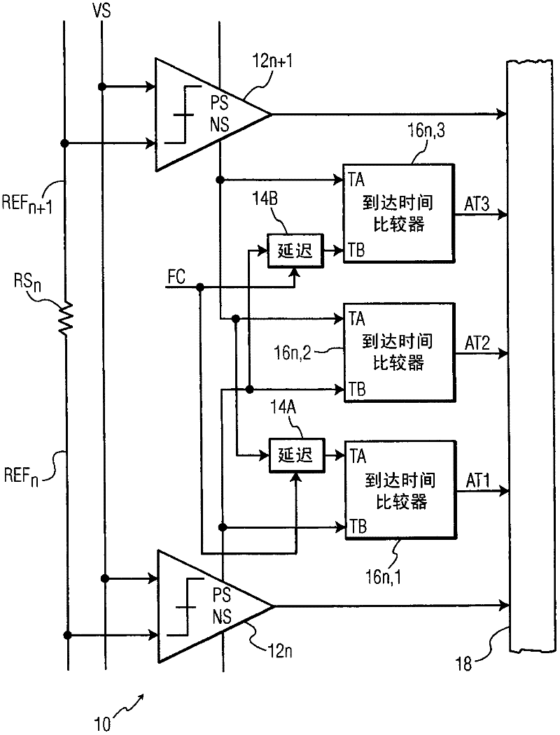
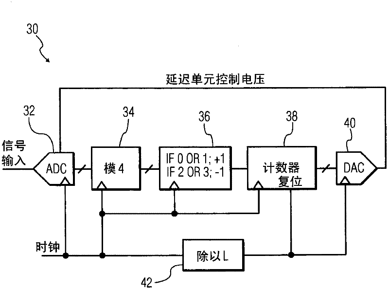
[0088] image 3 A functional block diagram of an example negative feedback calibration 30 according to one embodiment is shown. image 3Examples 30 include a flash ADC 32 according to any one of the disclosed M-bit flash ADC embodiments, such as figure 1 Combination of example 10 structure, modulo-4 event detector 34, counter increment / decrement unit 36, counter 38, digital / analog converter (DAC) 40 and divide-by-L (divide-by-L) reset unit 42.

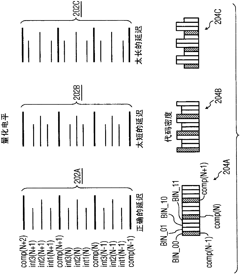
[0089] refer to image 3 , according to one aspect, the modulo-4 event detector 34 detects the operation of the binary output of the ADC 32, and in one example, if it is as figure 2 A binary 1 or a binary 0 sample, shown in item 204A, is in an outer bank such as BIN_00 or BIN_11 and the counter 36 is incremented. If it is a binary 2 or binary 3 sample, then in the inner bank such as BIN_01 or BIN_10 and the counter 36 is decremented.

[0090] Feedback the output of the counter 36 to control the delay, e.g. figure 1 CD 14A and 14B...


PUM


Abstract

An input signal is compared to 2N - 1 reference voltages to generate 2N - 1 corresponding binary valued comparison signals, delaying at least one of the comparison signals by a variable delay and detecting a difference in arrival time between the delayed signal and another comparison signal. A time interpolation signal encoding a plurality of bins within a least significant bit quantization level is generated, based on the detected difference in arrival time. An M-bit output data is generated based on the comparison signals and the time interpolation signal. A non-uniformity of a code density of the M-bit output data is detected, and based on the detecting the delaying is varied.

Description

[0001] This application is a continuation-in-part of US Patent Application No. 12 / 002,153 filed on December 13, 2007. technical field [0002] Embodiments relate generally to analog-to-digital conversion circuits, and more particularly to flash-type analog-to-digital conversion circuits. Background technique [0003] In basic form, an N-bit flash-type analog-to-digital (A / D) converter (hereinafter referred to as "ADC") has (2 N -1) comparators, arranged in cardinal order for comparing the same input signal with (2 N -1) Each major sequence of equally spaced reference voltages is compared. The voltage separation between each comparator and its adjacent high and / or low comparators is typically one least significant bit (LSB) of the N-bit output. [0004] In operation, all (2 N - 1) Comparators all receive the same sampling clock (typically periodic at the sampling rate) and generate a broadside output (broadside output) every clock pulse, for all comparators whose signal ex...

Claims


Application Information

Patent Timeline
Patent Type & Authority Applications(China)
IPC IPC(8): H03M1/20
CPCH03M1/1061H03M1/206H03M1/365H03M1/50H03M1/362
Inventor 米科·沃尔塔力康斯坦帝诺·帕拉
Owner NXP BV
Why Eureka
Try Eureka