Centrifugal fan

一种离心风扇、扇框的技术,应用在用于弹性流体的泵送装置的部件、非变容式泵、泵装置等方向,能够解决传统离心风扇900风量限制、气流阻滞、气流不能被顺畅地引导等问题

Inactive Publication Date: 2011-10-12
FU ZHUN PRECISION IND SHENZHEN +1
View PDF4 Cites 18 Cited by
  • Summary
  • Abstract
  • Description
  • Claims
  • Application Information

AI Technical Summary

Problems solved by technology

However, the applicant used CFD (Computational Fluid Dynamics, Computational Fluid Dynamics) software to perform flow field simulation analysis on the traditional centrifugal fan 900 and found that when the traditional centrifugal fan 900 was working, the air flow in the corner area 924 was blocked, forming a high-pressure dead zone. area, the airflow in the corner area 924 cannot be smoothly guided to the air outlet 920, so that the air volume of the traditional centrifugal fan 900 is limited

Method used


Image

  • Centrifugal fan
  • Centrifugal fan
  • Centrifugal fan

Examples


Embodiment Construction

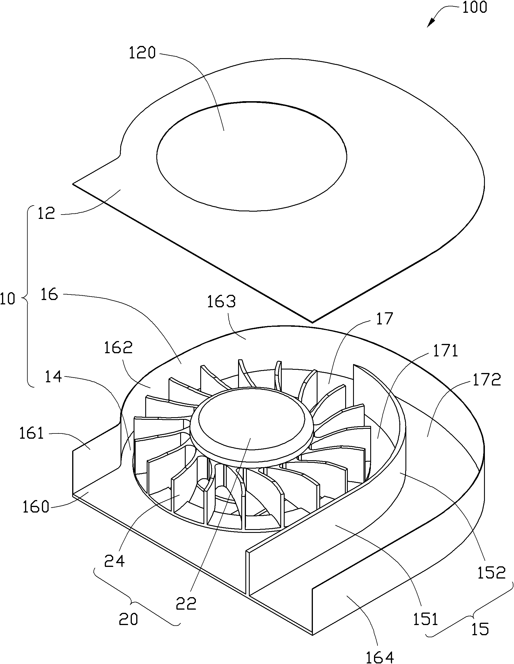
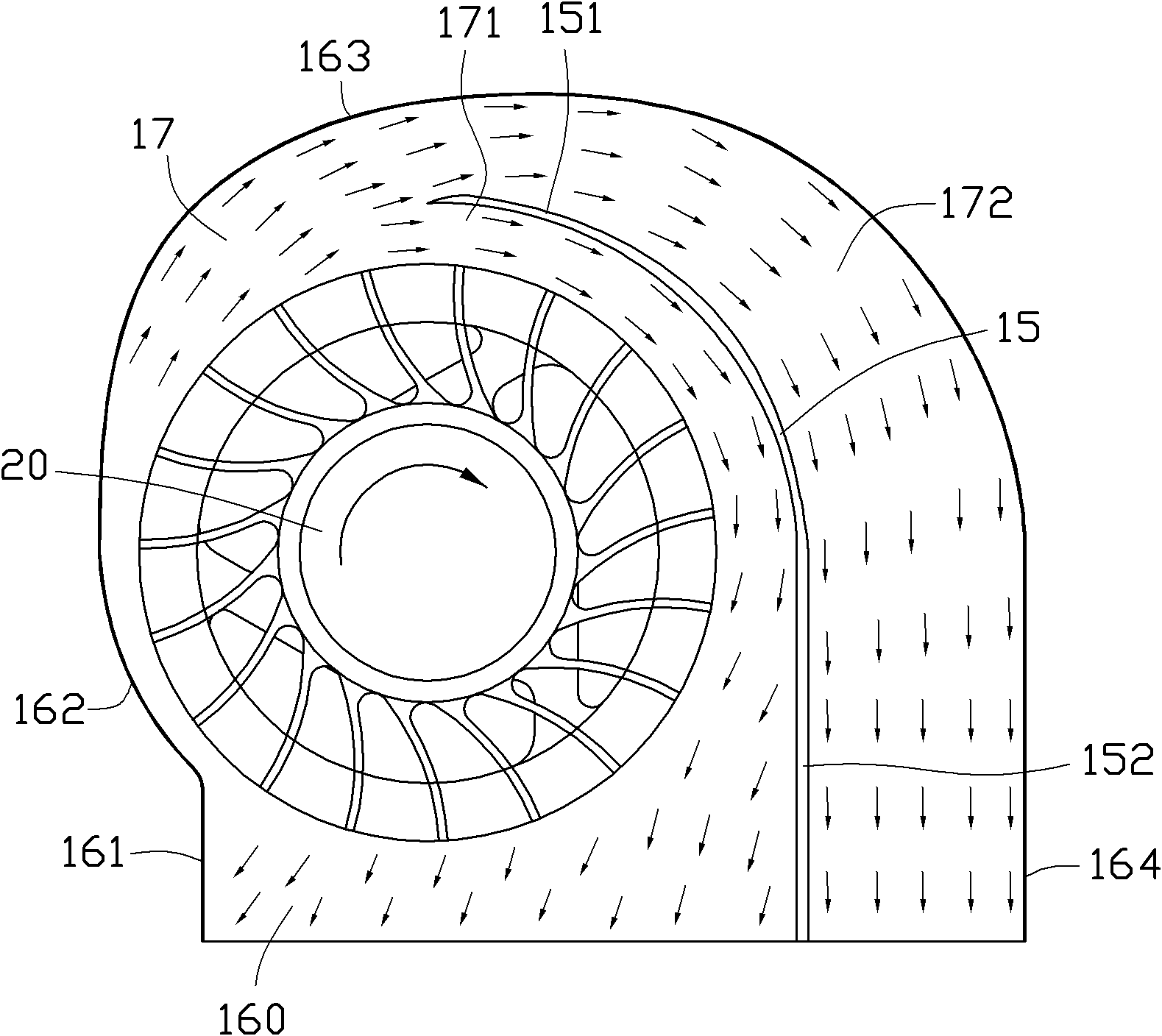
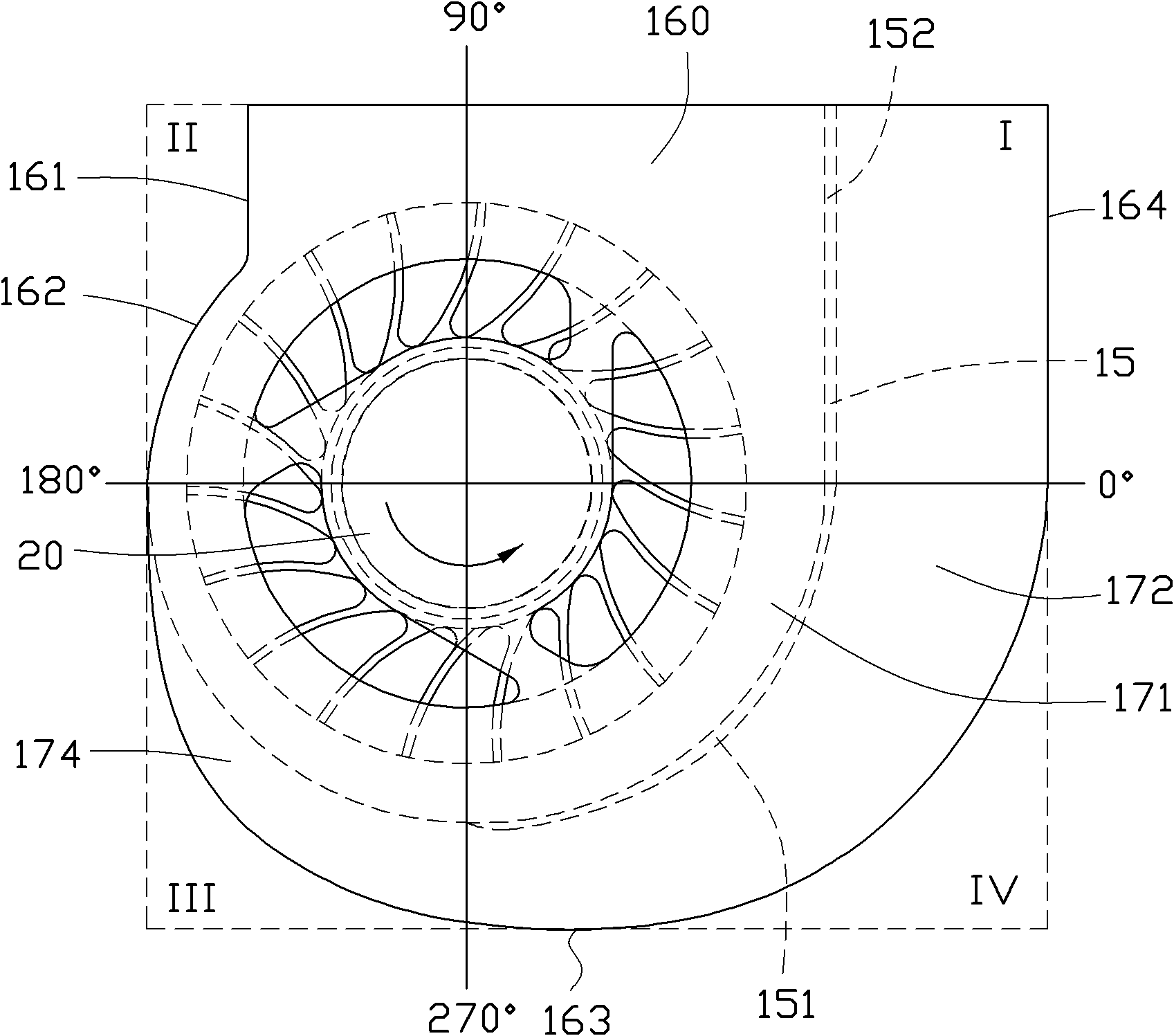
[0040] see figure 1 and figure 2 . The centrifugal fan 100 includes a fan frame 10 and an impeller 20 accommodated in the fan frame 10 . The impeller 20 includes a hub 22 and a plurality of blades 24 radially extending from the hub 22 . The fan frame 10 includes a top plate 12 , a bottom plate 14 opposite to the top plate 12 , and a scroll-shaped side wall 16 connected between the top plate 12 and the bottom plate 14 . The top plate 12 , the bottom plate 14 and the side wall 16 enclose and form an accommodating space, and the impeller 20 is accommodated in the accommodating space.

[0041] An air inlet 120 is formed in the center of the top plate 12 . The impeller 20 is rotatably mounted on the bottom plate 14 and faces the air inlet 120 . The side wall 16 vertically surrounds the outer periphery of the bottom plate 14 . In this embodiment, the side wall 16 is integrally formed with the bottom plate 14 . Of course, the side wall 16 and the bottom plate 14 can also be ...


PUM


Abstract

The invention relates to a centrifugal fan which comprises a fan frame and an impeller which is accommodated in the fan frame, wherein a channel is formed at the periphery of the impeller in the fan frame, one side of the fan frame is provided with an air outlet, the periphery of the fan frame is provided with an initial curve part and an expanded curve part connected with the initial curve part, the expanded curve part is placed at the rear side of the initial curve part along the direction of rotation of the impeller, the initial curve part extends along an Archimedean spiral or logarithmic spiral, the expanded curve part is placed on the outboard of the extended line obtained by extending the started curve part along the Archimedean spiral or logarithmic spiral, a guide plate is arranged in the fan frame, the guide plate extends from the air outlet to the channel, and the guide plate divides the channel into two airflow channels.

Description

technical field [0001] The invention relates to a centrifugal fan, in particular to a centrifugal fan used for heat dissipation of electronic components. Background technique [0002] At present, in a computer, a heat dissipation module composed of a heat conductor, a heat pipe, a heat sink group, and a centrifugal fan is often used to dissipate heat from electronic components. The heat conductor is attached to the electronic component to absorb the heat of the electronic component. The heat pipe transfers the heat absorbed by the heat conductor to the heat sink group. The airflow generated by the centrifugal fan blows the heat sink and exchanges heat with the heat sink to finally dissipate the heat. Therefore, the cooling module plays an extremely important role in ensuring the normal operation of electronic components. [0003] Figure 4 Shown is a conventional centrifugal fan 900 that includes a volute 92 and an impeller 94 housed within the volute 92 . An air outlet 92...

Claims


Application Information

Patent Timeline
Patent Type & Authority Applications(China)
IPC IPC(8): F04D29/42F04D29/44
CPCF04D25/0613F04D29/4246
Inventor 梁恩铭余方祥郭哲豪
Owner FU ZHUN PRECISION IND SHENZHEN
Why Eureka
Try Eureka