Driving circuit for LED (light emitting diode) lamp

A technology for driving circuits and LED lamps, applied in the layout of electric lamp circuits, electric light sources, lighting devices, etc., can solve the problems of low energy use efficiency, waste of raw materials, low power factor, etc., to achieve high energy use efficiency, prolong LED life, The effect of high power factor

Inactive Publication Date: 2011-10-12
上海古森实业有限公司
View PDF5 Cites 22 Cited by
  • Summary
  • Abstract
  • Description
  • Claims
  • Application Information

AI Technical Summary

Problems solved by technology

Compared with the energy used in LEDs, the energy consumed on the components of the driving device accounts for a relatively large proportion, and the energy utilization efficiency is low. To achieve 90%, hundreds of components must be used, which is extremely harmful to raw materials. Waste, and installation and commissioning production, the yield rate is low
The published Chinese patent application No. 200810140994.1 is a kind of LED drive circuit, because of its low power factor, it is not suitable for the current high-voltage drive LED lights

Method used


Image

  • Driving circuit for LED (light emitting diode) lamp
  • Driving circuit for LED (light emitting diode) lamp
  • Driving circuit for LED (light emitting diode) lamp

Examples


Embodiment Construction

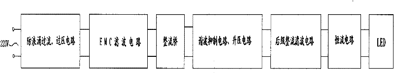
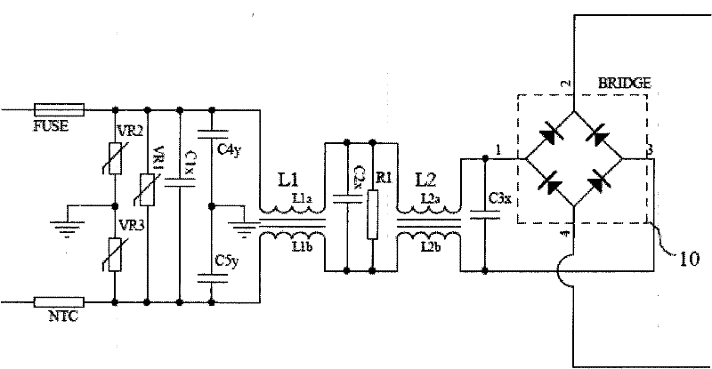
[0015] refer to figure 1 , Anti-surge overcurrent, overvoltage circuit input terminal externally connected to 220V mains, when the mains passes through the anti-surge overcurrent, overvoltage circuit device, this circuit can effectively suppress the instantaneous large current and instantaneous high voltage in the mains , so that the current and voltage are maintained within a safe range, the output of the anti-surge overcurrent and overvoltage circuit is connected to the input of the EMC filter circuit, the output of the EMC filter circuit is connected to the input of the rectifier bridge 10, and the output of the rectifier bridge 10 The terminal is connected to the input terminal of the harmonic suppression circuit and the boost circuit. When the mains electricity passes through the harmonic suppression circuit and the boost circuit, the voltage will increase, and the harmonic suppression circuit, the boost circuit and the post-stage rectification filter circuit , a constant...


PUM


Abstract

The invention relates to a driving circuit for an LED (light emitting diode) lamp. The driving circuit comprises an anti-surge overflow and overvoltage circuit, an EMC (electro magnetic compatibility) filter circuit, a rectifier bridge, a harmonic suppression circuit, a boosted circuit, a backward-stage rectifier filter circuit and a constant current circuit, wherein the input end of the anti-surge overflow and overvoltage circuit is externally connected with a commercial power network, and the output end of the constant current circuit is externally connected with the LED lamp. According to the invention, the low voltage power supply in the prior art is changed into a high voltage power supply for the LED lamp; and meanwhile, a switching converter can be omitted, the energy consumption when the switching converter is started and closed can be reduced, the power factor and the energy utilization ratio can be improved, and the purposes of energy conservation and environmental friendliness can be achieved.

Description

technical field [0001] The present invention relates to the field of LED lighting, in particular to the field of LED components, in particular to a driving circuit for LED lighting. Background technique [0002] At present, LEDs are widely used in municipal lighting fields such as street lamps and engineering and commercial lighting fields due to their long life, low energy consumption, no pollution, and easy color control. There are many kinds of LED driving devices at present, but all of them are low-voltage output. The energy needs to be converted by the switching transformer. When the switching transformer is started and switched off, the energy loss is large. Compared with the energy used in LEDs, the energy consumed on the components of the driving device accounts for a relatively large proportion, and the energy utilization efficiency is low. To achieve 90%, hundreds of components must be used, which is extremely harmful to raw materials. Waste, and installation and...

Claims


Application Information

Patent Timeline
Patent Type & Authority Applications(China)
IPC IPC(8): H05B37/02
Inventor 吴春林贺贤逊
Owner 上海古森实业有限公司
Why Eureka
Try Eureka