
Vehicle front-end for mounting to the front face of a track-bound vehicle, in particular a rail vehicle

A technology for rail vehicles and railway vehicles, which is applied to railway car body components, railway vehicle wheel guards/buffers, railway car bodies, etc., and can solve car body structure deformation, car body damage, and insufficient shock absorption effect of shock absorbers and other problems to achieve the effect of avoiding collapse and improving hardness

Active Publication Date: 2011-10-12
VOITH PATENT GMBH
View PDF2 Cites 17 Cited by
  • Summary
  • Abstract
  • Description
  • Claims
  • Application Information

AI Technical Summary

Problems solved by technology

[0007] When a side buffer element or a crash box is usually placed on the front of a rail vehicle as a shock absorber, these elements absorb or disperse at least part of the impact force, and the shock absorption effect that such a shock absorber can achieve in high-speed impacts is less than Not enough to keep the hull from being damaged
Especially when the shock absorption capacity of the side buffer elements or the crash box is exhausted, the car body structure of the driver's cab or passenger area will be greatly deformed, so that sufficient living space for the driver and passengers cannot be guaranteed, which has great risks. risk

Method used


Image

  • Vehicle front-end for mounting to the front face of a track-bound vehicle, in particular a rail vehicle
  • Vehicle front-end for mounting to the front face of a track-bound vehicle, in particular a rail vehicle
  • Vehicle front-end for mounting to the front face of a track-bound vehicle, in particular a rail vehicle

Examples


Embodiment Construction

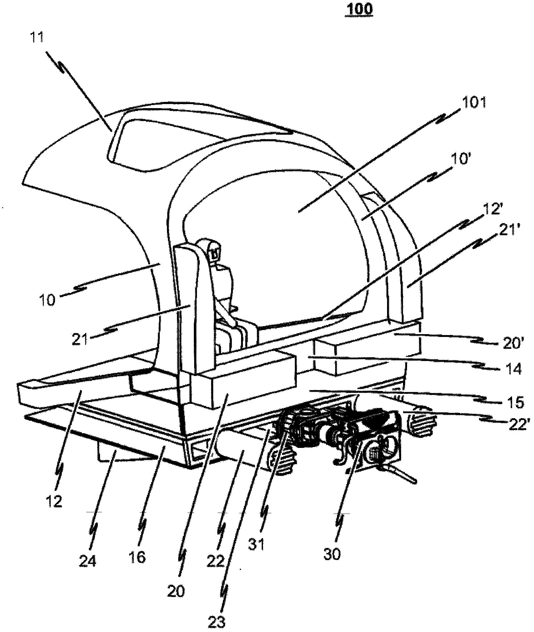
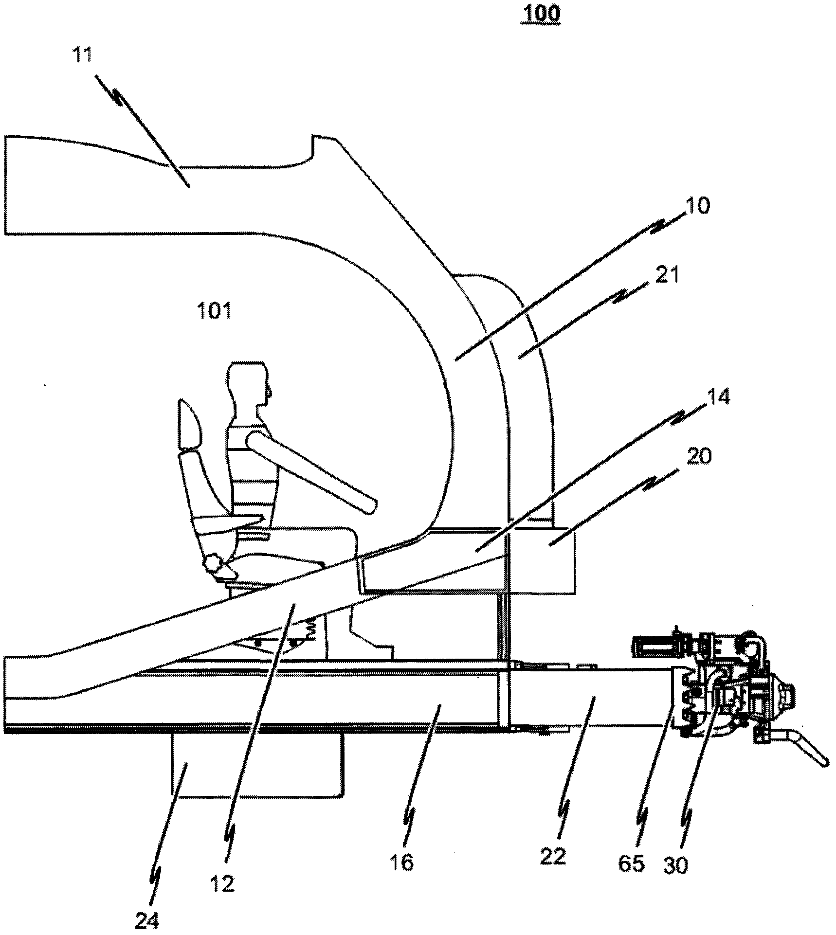
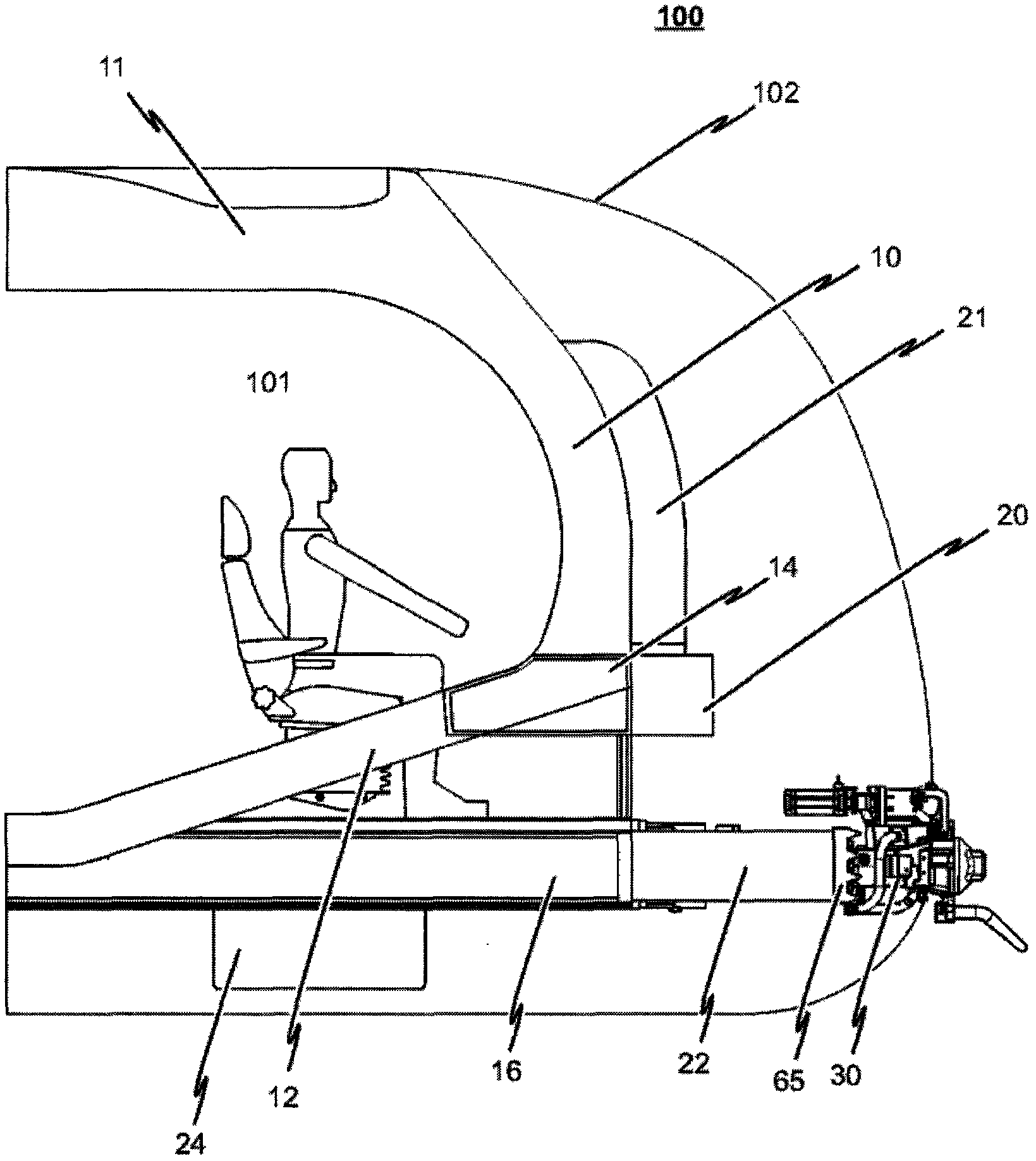
[0069] The vehicle front module structure 100 used in the vehicle front module provided in the first embodiment of the present invention will be described below with reference to the accompanying drawings.

[0070] figure 1 It is a schematic diagram of the vehicle front module structure 100 in the first embodiment of the present invention. figure 2 for figure 1 A schematic side view of the front module structure 100 of a medium vehicle. image 3 For the first embodiment with figure 1 or figure 2 Schematic side view of the vehicle front module in the middle vehicle front module structure 100 and implying the exterior design 102 .

[0071] Correspondingly, the vehicle front module structure 100 in this embodiment is designed to be installed at the front of the rail vehicle (not shown). The vehicle front module structure 100 is entirely composed of structural elements, cf. Figure 4-18 , the structural elements will be described in detail below. These structural elements...


PUM


Abstract

The invention relates to a vehicle front-end with a vehicle front-end structure (100) for mounting to the front face of a track-bound vehicle, in particular a rail vehicle, wherein the vehicle front-end structure (100) is completely made of structural elements of fibre composite material or sandwich structures of fibre composite material. The structural elements forming the vehicle front-end structure (100) comprise first structural elements (10, 10', 11, 12, 12', 14, 15, 16) which are directly connected to each other and configured in such a manner that a deformation-resistant, self-supporting head structure is formed for receiving a vehicle driver's stand (101). The structural elements forming the vehicle front-end structure (100) further comprise second structural elements (20, 20', 21, 21', 22, 22', 23, 24, 24') which are connected to the first structural elements (10, 10', 11, 12, 12', 14, 15, 16) and are configured in such a manner that at least a part of the impact energy (collision energy), which is generated in the event of a collision of the track-bound vehicle due to a transmission of impact forces and is introduced into the structure (100), is absorbed by at least a partial irreversible deformation or at least a partial destruction of the second structural elements (20, 20', 21, 21', 22, 22', 23, 24, 24').

Description

technical field [0001] The invention relates to a front module with a vehicle front frame mounted at the front of a rail vehicle, wherein the frame consists entirely of structural elements made of fiber-reinforced plastic. Background technique [0002] According to the patent application document GB2411630A published by the British Patent Office, a cabin frame of a railway vehicle is disclosed, the frame is composed of frame elements forming the front, bottom, top and side of the cabin. This known frame is provided with a plurality of flexible regions. When a rail vehicle equipped with such a frame vehicle front module collides with another rail vehicle or an obstacle, the flexible area is bent and deformed, so that the frame can be adapted to the shape of the impact obstacle, and the frame withstands the impact during the impact. Impact energy can be at least partially dissipated. [0003] In addition, according to the cabin of a rail vehicle disclosed in the patent appli...

Claims


Application Information

Patent Timeline
IPC IPC(8): B61D15/06
CPCB61C17/04B61D15/06B61D17/06B61G11/16B61F19/04
Inventor 安德里亚斯·海尼许莱内尔·海瑟乌维·北卡萨沙·恩德
Owner VOITH PATENT GMBH
Learn More