
Lifting apparatus for ship

A technology for lifting equipment and ships, applied in the direction of ship lifting devices, vertical lifting ship machinery, water conservancy projects, etc., can solve the problems of complex overall structure, inconvenient and free, high production cost, etc., to simplify the structure, reduce the weight of the structure, The effect of easy operation

Inactive Publication Date: 2011-10-19
吴平平
View PDF3 Cites 12 Cited by
  • Summary
  • Abstract
  • Description
  • Claims
  • Application Information

AI Technical Summary

Problems solved by technology

[0002] In the past, there were many problems in the traditional lifting equipment for ships, such as its own poor safety performance, complex overall structure and heavy weight, and it was inconvenient and easy to operate, which in turn led to the traditional lifting equipment used for ships. The production cost of the equipment becomes high, its service life is low, and its maintenance is also more troublesome

Method used


Image

  • Lifting apparatus for ship
  • Lifting apparatus for ship
  • Lifting apparatus for ship

Examples


Embodiment Construction

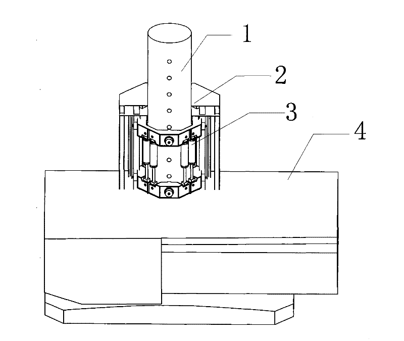
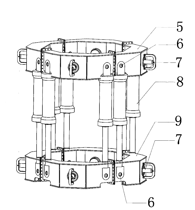
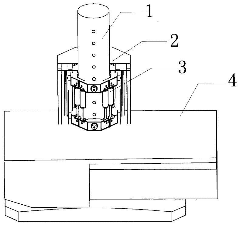
[0012] The present invention will be further described below in conjunction with all accompanying drawings, and the preferred embodiment of the present invention is: a kind of lifting equipment for ship described in this embodiment, it comprises spud can 1, installation tower 2, ring beam type hydraulic pressure Lifting device 3, hull 4, wherein, the spud shoe 1 of the present invention is located in the ring beam hydraulic lifting device 3, and the spud shoe 1 is provided with four rows of evenly arranged pin holes, which are used to cooperate with the ring beam hydraulic lifting device The bolt cylinder 7 on the 3 is matched, and then the spud shoe 1 of the present invention is connected with the ring beam hydraulic lifting device 3 through the bolt cylinder 7; the installation tower 2 is fixedly connected with the hull 4; the ring beam hydraulic lifting device 3 passes through The elastic pad is connected with the installation tower 2, and the ring beam type hydraulic liftin...


PUM


Abstract

The invention provides a lifting apparatus for ships which comprises a pile shoe, an installation tower, a circular-beam hydraulic lifting device, and a ship body; the installation tower is fixedly connected with the ship body; the circular-beam hydraulic lifting device is connected to the installation tower by an elastic cushion, and the circular-beam hydraulic lifting device is located between the installation tower and the ship body; the pile shoe is located in the circular-beam hydraulic lifting device, and is provided with a pin hole at the peripheral part for matching a bolt oil cylinder on the circular-beam hydraulic lifting device; the pile shoe is connected with the circular-beam hydraulic lifting device by the bolt oil cylinder; the circular-beam hydraulic lifting device comprises an upper circular beam, a connecting pin, a bolt oil cylinder, a lifting oil cylinder, a lower circular beam, wherein the lifting oil cylinder is located between the upper circular beam and the lower circular beam, and the lifting oil cylinder is connected with the upper circular beam and the lower circular beam by the connecting pin respectively; the bolt oil cylinder is disposed in the upper circular beam and the lower circular beam. By using the above scheme, the invention has good safety performance, and is simple in structure, convenient for operation, and light in weight.

Description

technical field [0001] The invention relates to the technical field of lifting equipment, in particular to a lifting equipment used for ships. Background technique [0002] In the past, there were many problems in the traditional lifting equipment for ships, such as its own poor safety performance, complex overall structure and heavy weight, and it was inconvenient and easy to operate, which in turn led to the traditional lifting equipment used for ships. The production cost of the equipment becomes high, its service life is short, and its maintenance is also relatively troublesome. In a word, due to the many problems of the traditional lifting equipment used for ships, it is imperative to improve it. Contents of the invention [0003] The object of the present invention is to overcome the disadvantages of the prior art and provide a lifting device for ships with simple and reasonable structure, high safety performance, low production cost, free transmission and convenien...

Claims


Application Information

Patent Timeline
IPC IPC(8): E02C5/00
CPCE02B17/0872E02B17/0809
Inventor 陆军
Owner 吴平平
Learn More