Fuel high-pressure pump applied in internal combustion engine

A technology of high-pressure pump and internal combustion engine, applied in the direction of fuel injection pump, fuel injection device, special fuel injection device, etc., can solve the problem of short switching time of the quantity control valve, and achieve the effect of simplifying the cost

Inactive Publication Date: 2011-10-19
ROBERT BOSCH GMBH
View PDF7 Cites 4 Cited by
  • Summary
  • Abstract
  • Description
  • Claims
  • Application Information

AI Technical Summary

Problems solved by technology

The switching times of the volume control valves used for this are very short due to the speed-synchronous control

Method used


Image

  • Fuel high-pressure pump applied in internal combustion engine
  • Fuel high-pressure pump applied in internal combustion engine
  • Fuel high-pressure pump applied in internal combustion engine

Examples


Embodiment Construction

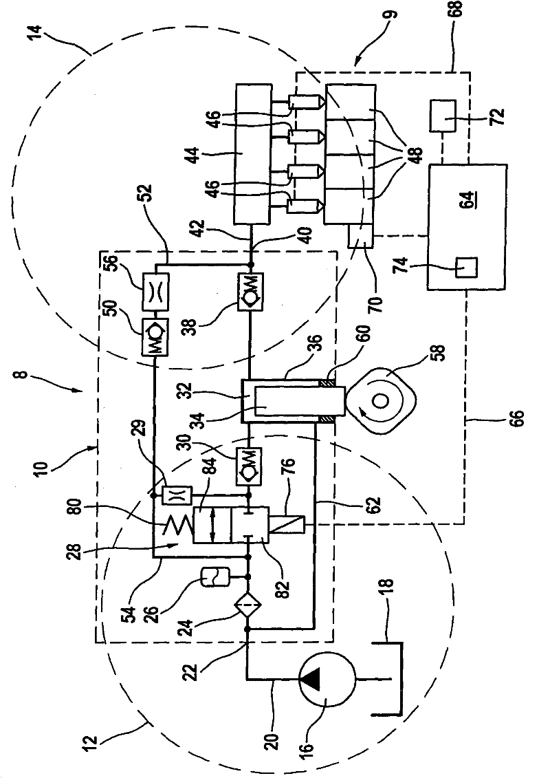
[0019] figure 1 A fuel system 8 for an internal combustion engine 9 is shown, provided with a high-pressure fuel pump 10 . The fuel system 8, as will also be described, is divided into figure 1 A low pressure region 12 is shown on the left and a high pressure region 14 is shown on the right. A delivery pump 16 arranged in the low-pressure region 12 pumps fuel with delivery pressure from the fuel storage container 18 via a low-pressure line 20 into an inlet connection 22 of the high-pressure fuel pump 10 . A filter 24 and a pressure damper 26 are arranged in the low-pressure region 12 of the fuel. The pressure damper 26 damps pressure fluctuations present on the low-pressure side of the high-pressure fuel pump 10 and enables a high delivery rate also at high rotational speeds and cam speeds.

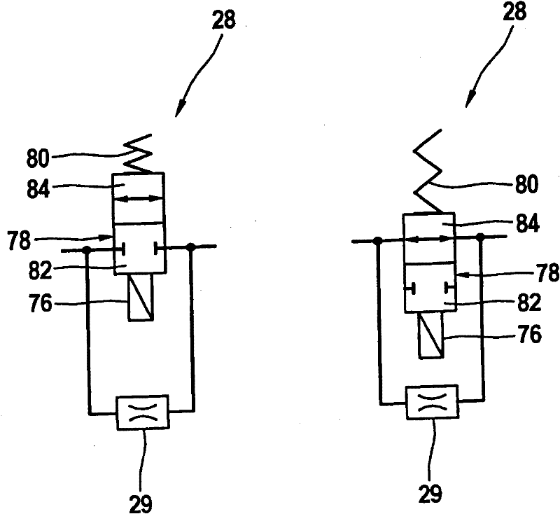
[0020] Fuel is sucked into a working chamber 32 of the high-pressure fuel pump 10 via the switching valve 28 and subsequently an inlet valve 30 . In this connection, the switching val...


PUM


Abstract

The utility model relates to a directly-injecting fuel high-pressure pump (10) applied in an internal combustion engine (9). The pump is provided with a low-pressure area (12) and a quantity control device. The quantity control device comprises a switch valve (28). The switch valve which is equipped on the upstream of a feed inlet valve (22) of the fuel high-pressure pump (10) comprises at least one opened first switching position (84) and one closed second switching position (82). It should be noted that a flow passage restrictor (29) which is in parallel connection with the switch valve (28) is equipped on fluids.

Description

technical field [0001] The invention relates to a high-pressure fuel pump for an internal combustion engine using direct injection according to the preamble of claim 1 . Furthermore, the subject matter of the invention relates to a method of operating a high-pressure fuel pump for an internal combustion engine with direct injection, a control and / or regulation device and a computer program according to the preambles of the corresponding independent independent claims. Background technique [0002] Current fuel systems for internal combustion engines with direct injection, known for example from DE 10 2007 010 502 A1, generally have a quantity-regulated fuel high-pressure pump in the inlet area (low-pressure area), wherein the quantity regulation is essentially via the fuel high-pressure pump The operation of an inlet valve synchronized with the rotational speed is achieved. A very precise quantity regulation can thus be achieved. The switching times of the quantity regulat...

Claims


Application Information

Patent Timeline
Patent Type & Authority Applications(China)
IPC IPC(8): F02M59/46F02M59/34
CPCF02M59/466F02D41/3845F02M59/34F02M63/0265F02M2200/18
Inventor B·施罗德B·普富尔
Owner ROBERT BOSCH GMBH
Why Eureka
Try Eureka