Electrical machine and permanent-magnet

一种永磁体、机器的技术,应用在磁路、风能发电、电气元件等方向,能够解决困难且昂贵等问题

Active Publication Date: 2011-10-19
SIEMENS GAMESA RENEWABLE ENERGY AS
View PDF5 Cites 13 Cited by
  • Summary
  • Abstract
  • Description
  • Claims
  • Application Information

AI Technical Summary

Problems solved by technology

Manufacturing such geometries is difficult and expensive

Method used


Image

  • Electrical machine and permanent-magnet
  • Electrical machine and permanent-magnet
  • Electrical machine and permanent-magnet

Examples


Embodiment Construction

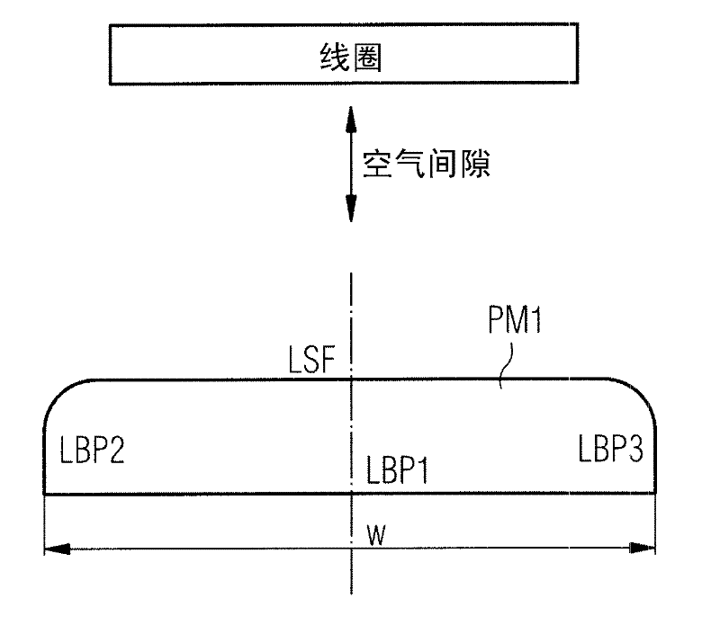
[0043] figure 1 A cross-sectional view of a permanent magnet PM1 is shown, which is shaped according to the invention.

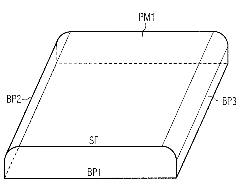
[0044] The cross-section of the permanent magnet PM1 comprises three linear segments LBP1, LBP2, LBP3. These segments LBP1, LBP2, LBP3 can belong to the following figure 2 Shown are rectangular areas BP1, BP2, BP3.

[0045] The cross-section of the permanent magnet PM1 also contains the line LSF. The line LSF is shaped according to Bezier functions at its edges, while the edges are assigned to the transition region between the surface of the magnet and the adjacent substrate plane, as in the following figure 2 shown.

[0046] Thus, the line LSF is transformed into adjacent linear segments LBP2 and LBP3 by means of Bezier functions or Bezier curves.

[0047] The surface line LSF belongs to the surface SF of the permanent magnet PM1, as shown in the following figure 2 shown.

[0048] The shaped surface is aligned with the coil and the air gap between...


PUM


Abstract

The invention relates to an electrical machine, which contains permanent magnets and to the permanent magnets being used. The invention especially relates to a synchronous machine. According to the invention the electrical machine contains a permanent magnet and a coil. The coil is arranged in a way that it interacts with the permanent magnet via an air gap, which is located between the permanent magnet and the coil. The permanent magnet and the coil are arranged in a way that electrical power is generated in the coil when the permanent magnet or the coil is moved in their relative position to each other. The permanent magnet contains a surface, which is aligned to the coil and to the air gap in a way, that magnetic forces of the permanent magnet interact via the surface and the air gap with the coil by a magnetic flux density distribution. The permanent magnet contains a surface, a base plane and a transition area. A first side of the surface is connected with the adjacent base plane via the transition area. The cross-section of the transition between the surface and the adjacent base plane is determined by a Bezier function, which is assigned to and defined by three points. A first point is assigned to the surface, while a second point is assigned to the base plane and while a third point is assigned to the transition area, which is between the surface and the base plane.

Description

technical field [0001] The invention relates to electric machines comprising permanent magnets, and to the permanent magnets used. The invention particularly relates to synchronous machines. Background technique [0002] An electric machine, such as a generator, contains a plurality of permanent magnets that interact with at least one coil to generate electrical energy. For the magnets used, there are compromises. At least some of the following problems must be minimized or even avoided: [0003] First, the magnetic force (field strength) of a magnet will vary due to its individual characteristics and tolerances. Periodic torque ripple will occur if the machine is in the "no load", "idle" or "full load" state. [0004] Secondly, for reasons of steadily increasing costs, there is a need to minimize the number and / or size of the permanent magnets used. [0005] This torque is denoted as "cogging torque" if the machine is in an "unloaded" state and as "ripple torque" if th...

Claims


Application Information

Patent Timeline
Patent Type & Authority Applications(China)
IPC IPC(8): H02K1/06
CPCH02K1/278H02K29/03Y02E10/72
Inventor A.汤玛斯
Owner SIEMENS GAMESA RENEWABLE ENERGY AS
Why Eureka
Try Eureka