Variable valve gear and method of controlling same

A control method and technology of valve device, applied in valve device, electrical control, engine control and other directions, can solve the problems of timing deviation of suction valve fully closed, delayed return of spool valve, slow return, etc., to prevent slippage Action delay, effect of suppressing action delay

Inactive Publication Date: 2011-10-19
KOMATSU LTD
View PDF6 Cites 4 Cited by
  • Summary
  • Abstract
  • Description
  • Claims
  • Application Information

AI Technical Summary

Problems solved by technology

[0008] However, if the electromagnetic on-off valve disclosed in Patent Document 1 is maintained in the closed state, the oil film on the spool portion of the electromagnetic on-off valve is used up, and the operation may become unstable at the initial movement.
[0009] That is, after maintaining the closed state of the electromagnetic on-off valve, if the oil film of the spool valve portion is used up during the initial on-off operation of the electromagnetic on-off valve, the spool valve of the spool valve portion cannot operate smoothly. , especially during the cut-off action, the return of the slide valve is delayed (slowly), so that the timing of the full closing of the intake valve is greatly deviated. As a result, the compression ratio changes, which may lead to incomplete combustion
[0010] In addition, if the return of the slide valve is slow (delayed) so that the timing of the full closing of the intake valve is delayed, the intake valve may collide with the engine piston.

Method used


Image

  • Variable valve gear and method of controlling same
  • Variable valve gear and method of controlling same
  • Variable valve gear and method of controlling same

Examples


Embodiment Construction

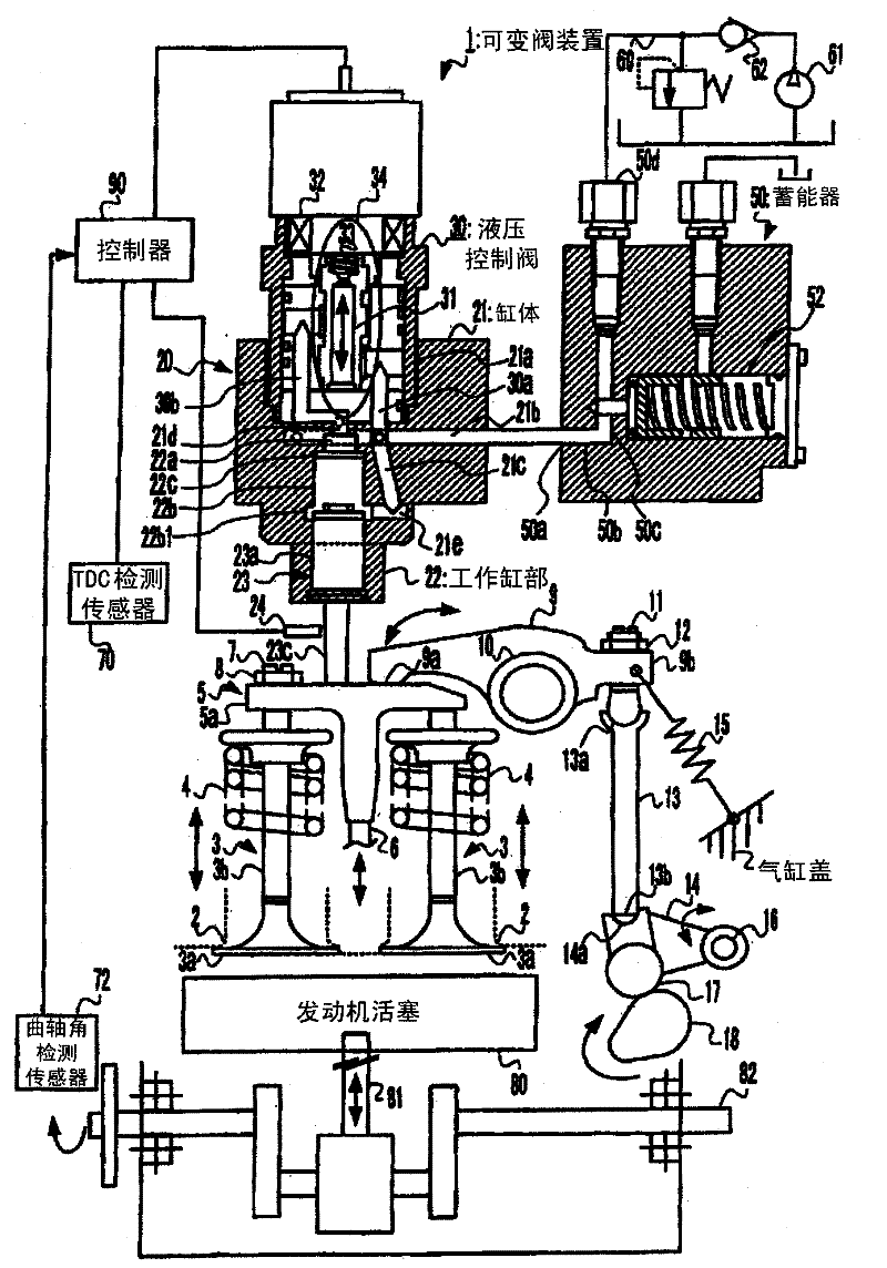
[0039] Hereinafter, an embodiment of the variable valve device and its control method according to the present invention will be described in detail with reference to the drawings.

[0040] figure 1 It is a conceptual diagram showing the variable valve device 1 according to the present invention. In this embodiment, it is assumed that the variable valve device 1 is used in a 4-cycle diesel engine. However, the variable valve device 1 according to the present invention The device is not limited to this embodiment.

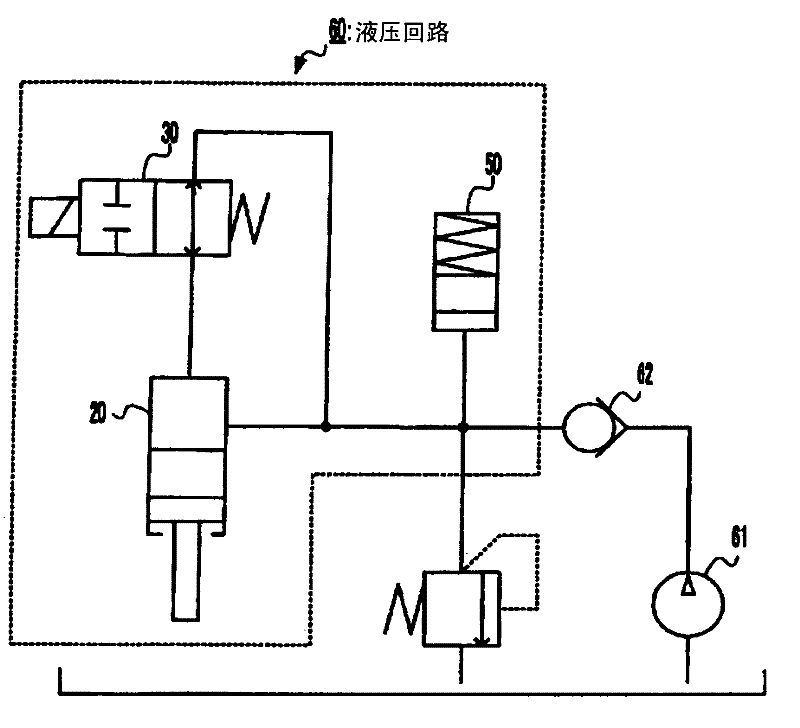
[0041] Such as figure 1 As shown, the variable valve device 1 includes a controller for controlling the variable valve device (hereinafter, simply referred to as a controller) 90, a gap sensor 24, a TDC (=Top Dead Center, top dead center) detection sensor 70, a crank angle detection sensor 72, constitute the hydraulic circuit 60 described later (refer to figure 2 ) hydraulic actuator 20, hydraulic control valve 30, accumulator 50 and diesel engine.

[0042] The...


PUM


Abstract

A variable valve gear and a method of controlling the variable valve gear, wherein, in order to prevent a shortage of oil film in a spool section, only the spool of a solenoid on / off valve is moved at a timing not affecting operation of an intake valve, to thereby stabilize operation of the solenoid on / off valve. A variable valve gear comprises: a hydraulic actuator provided with a valve gear mechanism for moving an air intake valve to open or close an air intake opening and also with a piston rod section for preventing the air intake valve from moving; a hydraulic control valve for controlling hydraulic oil supplied to or discharged from the hydraulic actuator, the hydraulic control valve having a valve member and a slide surface on which the valve member slides, the valve member being configured so as to move between a prevented position at which the piston rod section of the hydraulic actuator is prevented from operating and a released position at which the piston rod section is not prevented from operating; and a means for performing control valve stabilizing control for sliding the valve member of the hydraulic control valve when the air intake valve is being totally closed by the air intake valve, and the means also performing variable valve control for sliding, after the control valve stabilizing control is performed and while the air intake valve is being engaged in closing movement, the valve member to the prevented side to prevent the piston rod section from operating, stopping the closing movement of the air intake valve to thereby change the timing at which the air intake opening is totally closed.

Description

technical field [0001] The present invention relates to a variable valve device and a control method thereof. Background technique [0002] Conventionally, it is known that an engine mounted on a vehicle is equipped with a variable valve device that controls the opening and closing timing of the intake valve or the exhaust valve according to the operating state of the engine, and adjusts the amount of intake air or exhaust air. quantity. [0003] In this variable valve device, an electric motor or hydraulic pressure is used as a driving source, and a hydraulic drive type variable valve device driven by hydraulic pressure controls the flow of hydraulic oil to operate the variable valve. [0004] For example, a variable valve arrangement is provided which utilizes a directional control valve to prevent fluid from flowing out of a fluid actuator following a rocker arm at a prescribed timing, whereby the fluid actuator stops acting on The rocker arm maintains the open state of...

Claims


Application Information

Patent Timeline
Patent Type & Authority Applications(China)
IPC IPC(8): F01L9/02F01L9/10
CPCF01L1/267F01L13/0015F01L2001/34443F01L2013/0089F02D13/0226F02D13/0269F02D41/20F02D2041/001Y02T10/12F01L9/10
Inventor 佐藤悦郎橘英明久田阳平太田一男
Owner KOMATSU LTD
Why Eureka
Try Eureka