Rotating apparatus

A technology of rotating equipment and equipment, which is applied in the direction of mechanical equipment, ocean energy power generation, hydropower generation, etc., to achieve the effect of preventing excessive mechanical stress and strain

Inactive Publication Date: 2011-10-19
INVENTUA
View PDF4 Cites 5 Cited by
  • Summary
  • Abstract
  • Description
  • Claims
  • Application Information

AI Technical Summary

Problems solved by technology

[0014] In order to overcome the mentioned difficulties, it is an object of the present invention to provide an improved rotary device for exploiting the power of water flow, in particular the energy of undulating water flow and the energy of linear water flow, so as to eliminate or reduce the above-mentioned disadvantages

Method used


Image

  • Rotating apparatus
  • Rotating apparatus
  • Rotating apparatus

Examples


Embodiment Construction

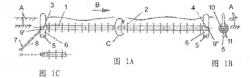
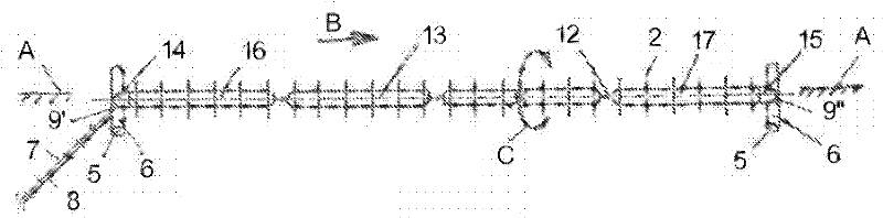
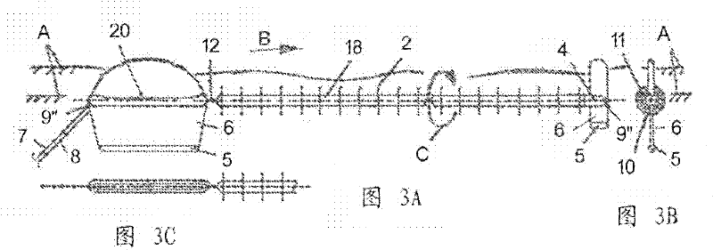
[0063] Refer to Figure 1 to Image 6 , shows a device in a wave environment with a horizontal plane A, where the waves propagate in a direction B parallel to the length direction of the device. The watertight floating rotors 1 , 13 , 18 , 21 , 28 , 29 , 30 are rotated in a circular direction of rotation C perpendicular to the length direction of the apparatus by drive means 2 which extend the rotors. The rotor is anchored by the main anchoring means 7 and is connected via a universal joint 9' in the first non-rotating end housing 3, 14, 20, 22 to wiring 8 for energy transmission, such as wiring for electrical energy transmission . A second non-rotating end housing 4, 15, 23 is provided at the distal end of the device, to which a further anchor 9" can be connected. The wiring 8 is flexibly guided through a universal joint 12 and is adapted to be provided at Rotating sleeve in non-rotating end housing. The rotor and non-rotating end housing house ballast tanks which can be fil...


PUM


Abstract

The present invention concerns a rotating apparatus related to water power, particularly related to wave power, and related to conversion of energy, for instance to generate electricity. The apparatus according to the invention may comprise one or more axially connected horizontally arranged floating or neutrally buoyant rotors that are driven by a number of fins that in turn are driven by wave waterflows and / or linear waterflows, said rotors being adapted for rotation,said rotation being non-changing and independent of the direction of the waterflows. The rotational energy is preferably converted to electricity by built-in generators. In addition, the apparatus comprises an arrangement so that the apparatus is adapted to move into a position corresponding to the direction of the waterflows.

Description

technical field [0001] The invention relates to hydropower and energy conversion, eg to generate electricity. Background technique [0002] Many hydraulic systems, especially floating systems, cannot handle stormy waves. Systems operating with plates of large area perpendicular to the direction of wave propagation are susceptible to large anchoring forces. In addition, systems that use anchoring forces to generate energy, so-called point absorbers, and systems that rely on suspensions, have problems associated with end fixation. [0003] It is known that not only linear but also wavy current energy can be used for power generation as disclosed in the following documents: [0004] WO 02 / 44558 A1 (Rossen) [0005] US 6036443A (Gorlov) [0006] DK 171714 (Stenberg) [0007] DE 102004060275 A1(Jobb) [0008] In addition, WO 2008 / 093037 A1 discloses an apparatus in which vanes rotate the body in response to the flow of fluid, thereby maintaining the angular momentum of the ...

Claims


Application Information

Patent Timeline
Patent Type & Authority Applications(China)
IPC IPC(8): F03B13/18
CPCF03B13/183F03B13/188F03B17/061F05B2240/311Y02E10/30Y02E10/20
Inventor 奥杰文德.博尔茨曼弗雷德.博尔茨斯蒂格.文德洛夫
Owner INVENTUA
Why Eureka
Try Eureka