Automatic rice seedling taking and feeding transplanter
A transplanting machine, fully automatic technology, applied in the field of agricultural machinery, can solve the problems of low work efficiency of picking and feeding seedlings, large number of assistants, etc., and achieve the effect of reducing labor costs and improving work efficiency
- Summary
- Abstract
- Description
- Claims
- Application Information
AI Technical Summary
Problems solved by technology
Method used
Image

Examples
Embodiment 1
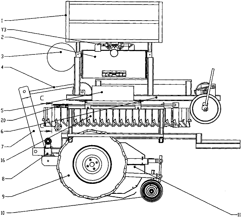
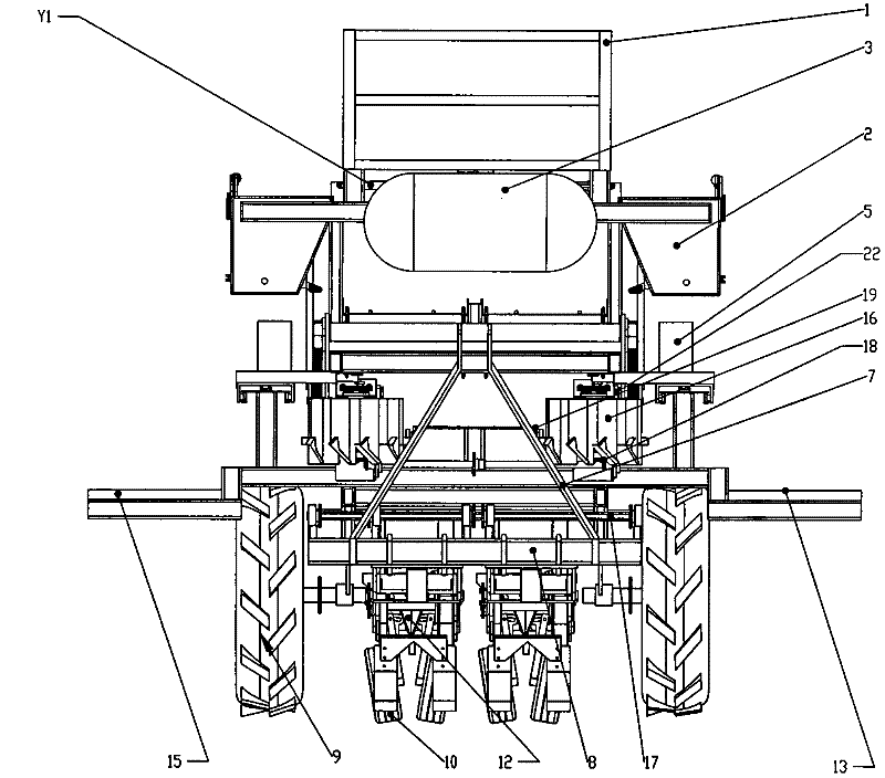
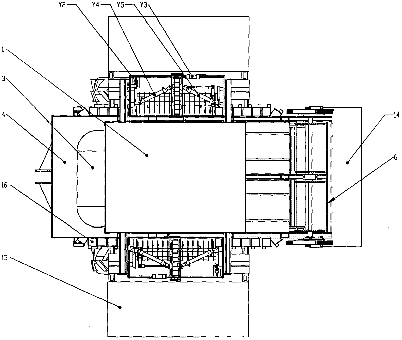
[0027] refer to figure 1 , 2 , 3, the full-automatic seedling transplanting machine for taking and feeding pots of the present invention is driven by a tractor, and the full-automatic transplanting machine for seedlings taking and feeding pots includes a seedling tray frame 1, a transporting seedling tray mechanism 6, an automatic seedling feeding mechanism 2, Seedling receiver 5, seedling guide cup 16. The staff standing on the rear pedal 14 takes out the seedling tray from the seedling tray rack 1 and places it on the transporting seedling tray mechanism 6, and pushes the seedling tray to the seedling picking position of the automatic seedling feeding bowl mechanism 2 by the transporting seedling tray mechanism 6 , the automatic feeding mechanism 2 takes out a plurality of pot seedlings from the seedling tray and feeds them into the seedling receiver 5, and the pot seedlings fall into the corresponding seedling guide cup 16 from the seedling receiver 5 under the action of t...
Embodiment 2
[0030] refer to Figure 4 , Figure 5 and Figure 7 , Figure 7 7-1 is a top view, and 7-2 is a side view. The seedling receiving device 5 includes a seedling receiving device compartment box 30, a seedling receiving device moving back and forth base plate 31, and a seedling receiving device moving left and right base plate 32. , Eccentric wheel track 33.
[0031] The seedling receiving device compartment box 30 is fixedly connected with the seedling receiving device moving back and forth base plate 31, the seedling receiving device compartment box 30 bottom through hole A, the through hole A passes through the seedling receiving device moving back and forth base plate 31, and the seedling receiving device moves the base plate left and right 32 is provided with a group of through holes B corresponding to the through holes A at the bottom of the seedling receiver compartment box 30 (such as Figure 7 Among them, eight seedling receiver compartment boxes 30 correspond to eig...
Embodiment 3
[0037] refer to Figure 8As shown, it is a schematic structural view (side view) of the conveying seedling tray mechanism 6, which includes a tray transfer handle 230, a speed-increasing gear set 24, and a flexible chain 25. promote( Figure 8 For upward promotion in the middle) shifting plate handle 230 can drive speed-up gear set 24, and speed-up gear set 24 drives flexible chain 25 to rotate, and the seedling dish that is placed on the flexible chain 25 is promptly pushed forward until getting the seedling position.
[0038] A disc transfer handle limiter 26 is also provided, and the disc transfer handle limiter 26 is used to control the stroke of the disc transfer handle 230 when it returns to its original position.
[0039] For example, the staff standing on the rear pedal 14 takes out the seedling tray from the seedling tray rack 1 and puts it on the flexible chain 25 of the seedling tray mechanism 6, and can move the tray handle 230 by the cylinder or manpower to drive...
PUM
 Abstract
Description
Claims
Application Information
 - R&D
- Intellectual Property
- Life Sciences
- Materials
- Tech Scout
- Unparalleled Data Quality
- Higher Quality Content
- 60% Fewer Hallucinations
Browse by: Latest US Patents, China's latest patents, Technical Efficacy Thesaurus, Application Domain, Technology Topic, Popular Technical Reports.
© 2025 PatSnap. All rights reserved.Legal|Privacy policy|Modern Slavery Act Transparency Statement|Sitemap|About US| Contact US: help@patsnap.com