Gas extraction method of cross hole drilling area of gas discharge laneway

A gas discharge roadway and gas drainage technology, which is applied in the direction of gas discharge, earthwork drilling, directional drilling, etc., can solve the problems of gas gushing, heavy construction workload of high drainage roadways, and long preparation time for recovery, etc.

Active Publication Date: 2011-10-26
CHINA UNIV OF MINING & TECH
View PDF9 Cites 51 Cited by
  • Summary
  • Abstract
  • Description
  • Claims
  • Application Information

AI Technical Summary

Problems solved by technology

However, this type of ventilation method has the following problems: ①The return air flow of the working face passes through the goaf, and as the working face advances, the ventilation resistance of the goaf changes greatly, which violates the "Coal Mine Safety Regulations" (hereinafter referred to as the "Regulations") regarding the mining work. The face air intake and return air must not pass through the goaf; ②The collapse of the roof of the mining face makes the ventilation resistance of the tail lane change greatly, the ventilation air volume is unstable, and the gas concentration changes greatly, so local fans are usually used for air supply , and its reliability is difficult to guarantee; ③The opening and closing of the gas drainage connection lane and drilling construction and other operations must be carried out frequently in the tail lane, which violates the provisions of the "Regulations" on the prohibition of production operations and installation of electrical equipment in the gas drainage tail lane; ④ This method is a gas control method based on "ventilation as the mainstay and drainage as the supplement". The ventilation method is mainly used to solve the gas gushing out of the working face, which is not in line with the current development trend of regional gas control technology.
However, in the early stage of recovery, before the high-level drainage roadway takes effect, the gas gushing out of the working face cannot be solved, and the construction workload of the high-level drainage roadway is relatively large, and the recovery preparation time is long

Method used


Image

  • Gas extraction method of cross hole drilling area of gas discharge laneway
  • Gas extraction method of cross hole drilling area of gas discharge laneway
  • Gas extraction method of cross hole drilling area of gas discharge laneway

Examples


Embodiment Construction

[0019] An embodiment of the present invention will be further described below in conjunction with accompanying drawing:

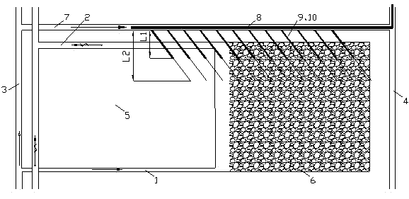
[0020] Such as figure 1 As shown, the method for gas drainage in the gas discharge lane of the present invention is based on the geological exploration information of the coal seam. A gas discharge roadway 7 parallel to the return airway 2 of the working face is excavated in the main roadway 3. The gas discharge roadway 7 can be used as the air inlet roadway adjacent to the mining face. The cross-sectional area of ​​the gas discharge roadway 7 is 5-8m 2 ; The distance between the gas discharge lane 7 and the return air lane 2 of the working face is 15-30m. Then excavate a mining area return air lane 4 parallel to the mining area track lane 3 at the tail of the gas discharge lane 7 and in the protection coal pillar of the working face, so that the air intake of the mining area track lane 3 enters the gas discharge lane 7 along the The return air lane 4 in ...


PUM


Abstract

The invention discloses a gas extraction method of a cross hole drilling area of a gas discharge laneway, comprising the following steps: tunnelling an mining area return airway parallel to a mining area track roadway at the tail part of the gas discharge laneway; arranging drill sites on the gas discharge laneway along the roof of a coal seam at intervals; respectively constructing multiple high-level drilling holes with different oblique angles and different lengths and a low-level hole in a worked out area direction in the middle and upper part of each drill site; arranging an extraction pipe after hole drilling construction in each drill site is finished; sealing the holes; and connecting the drilling holes in each drill site into the extraction pipe of the gas discharge laneway through an upper confluence pipe and a lower confluence pipe for extraction, thus realizing the safe production of a gas coal seam group. The method is safe and reliable, can effectively intercept pressure relief gas at an upper neighbor layer, effectively controls the gas from flowing out from a stope face, lowers the gas concentration of an upper corner, and ensures the safe production of the stope face.

Description

technical field [0001] The invention relates to a gas extraction method in a gas discharge roadway through a layer-crossing drilling area, especially a method suitable for relatively stable coal seam occurrence, an annual output of 1 million to 3 million tons, and a gas emission of 50 to 250 m 3 / min regional gas drainage of high gas working face. Background technique [0002] As the coal seam of the mine is gradually mined deeper, the gas pressure and gas content of the coal seam are increasing. In addition, the general application of the comprehensive mechanized top-coal caving mining technology has doubled the absolute gas emission of the working face. The acceleration of the advancing speed of the working face has resulted in a large amount of gas gushing out from the roof and falling coal in the goaf, and the gas often exceeds the limit in the upper corner of the working face, which has become a great hidden danger that threatens the safe production of the mining face ...

Claims


Application Information

Patent Timeline
Patent Type & Authority Applications(China)
IPC IPC(8): E21F7/00E21D9/00E21B7/06
Inventor 刘洪永程远平周红星翟清伟孔胜利刘清泉
Owner CHINA UNIV OF MINING & TECH
Why Eureka
Try Eureka