Detection feedback circuit

A technology for detecting feedback circuits and circuits, which is applied in the field of circuits, can solve problems such as component aging, increased working power, and damage, and achieve the effect of avoiding component damage

Inactive Publication Date: 2011-10-26
仝兴孚
View PDF1 Cites 9 Cited by
  • Summary
  • Abstract
  • Description
  • Claims
  • Application Information

AI Technical Summary

Problems solved by technology

[0002] During the use of the circuit, some components will increase the working power due to the increase of voltage or current or other reasons,

Method used


Image

  • Detection feedback circuit
  • Detection feedback circuit
  • Detection feedback circuit

Examples


Embodiment 1

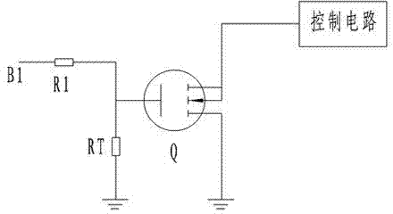
[0014] detection feedback circuit such as figure 2 shown. The drain of the field effect transistor Q is grounded, the source of the field effect transistor Q is connected to the control circuit, the control electrode of the field effect transistor Q is connected to the common end of the resistor R1 and the thermistor RT, the other end of the thermistor RT is grounded, and the resistor The other end of R1 is connected to power supply B1.

Embodiment 2

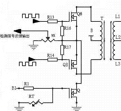
[0016] detection feedback circuit such as image 3 shown. The output terminals L1, L2 and L3 of the transformer T are connected to the load L, and the input terminals of the transformer T are respectively connected to the drain of the field effect transistor Q6, the power supply B, and the drain of the field effect transistor Q8. The control electrode of the field effect transistor Q6 inputs a pulse signal through the resistor R13, and the common terminal of the control electrode of the field effect transistor Q6 and the resistor R13 is connected to the resistor R16. The control electrode of the field effect transistor Q8 inputs a pulse signal through the resistor R14, and the common terminal of the control electrode of the field effect transistor Q8 and the resistor R14 is connected to the resistor R17. The other end of the resistor 17 is connected to the other end of the resistor 16 and also connected to one end of the sliding resistor WR. The end of the sliding resistor W...


PUM


Abstract

The invention relates to a circuit, and especially relates to a detection feedback circuit. The detection feedback circuit comprises a field effect transistor and a resistor R1, wherein a control electrode of the field effect transistor connects the resistor R1, and a source or drain electrode of the field effect transistor connects a control circuit. The detection feedback circuit is characterized by also comprising a thermistor, wherein the control electrode of the field effect transistor connects the thermistor. The invention is aimed at monitoring components temperature in real time and carrying out feedback control on components work voltage or current to stabilize work voltage or current of the components, guarantee normal work voltage or current of the components, prevent a temperature of the components working environment from rising too high, avoid damage of the components and prolong the service life of the components.

Description

technical field [0001] The invention relates to a circuit, in particular to a detection feedback circuit. Background technique [0002] During the use of the circuit, some components will increase the working power due to the increase of voltage or current or other reasons, resulting in the high temperature of the working environment of the components, which will easily cause aging and damage of the components. Contents of the invention [0003] The purpose of the present invention is to provide a device that can monitor the temperature of components in real time, and perform feedback control on the working voltage or current of components, so as to stabilize the working voltage or current of components, ensure the normal working voltage or current of components, and prevent components from The temperature of the working environment of the device rises too much to avoid damage to the components and prolong the service life of the components. [0004] The technical solutio...

Claims


Application Information

Patent Timeline
IPC IPC(8): G05D23/24G01K7/22
Inventor 仝兴孚
Owner 仝兴孚
Why Eureka
Try Eureka