
Machining method of roughness of seal groove

A processing method and sealing groove technology, applied in the field of seal processing, can solve the problems of cumbersome polishing process steps, not suitable for large-scale production and processing, and affecting processing efficiency, so as to reduce human factors, reduce processing costs, and achieve good processing quality Effect

Active Publication Date: 2013-03-13
中国航发湖南南方宇航工业有限公司
View PDF3 Cites 0 Cited by
  • Summary
  • Abstract
  • Description
  • Claims
  • Application Information

AI Technical Summary

Problems solved by technology

Workers' polishing process steps are cumbersome, which is largely limited by workers' skill level and workers' mood
There is a lot of chance in the polishing results, and it seriously affects the processing efficiency, so it is not suitable for large-scale production and processing

Method used


Image

  • Machining method of roughness of seal groove
  • Machining method of roughness of seal groove

Examples


Embodiment 1

[0018] A sealing groove roughness processing method, the steps are as follows:

[0019] (1) Selection of groove cutter: choose a groove cutter with a rake angle of 20° and a concave arc-shaped chip breaker, the elongation of the cutter bar is 4mm, and the cutting edge is ground to Ra0.4;

[0020] (2) Rigid clamping: When machining outer circular grooves, the clamping method of the spindle clamping the top support is adopted; when machining inner hole grooves, the clamping method of center frame support is adopted;

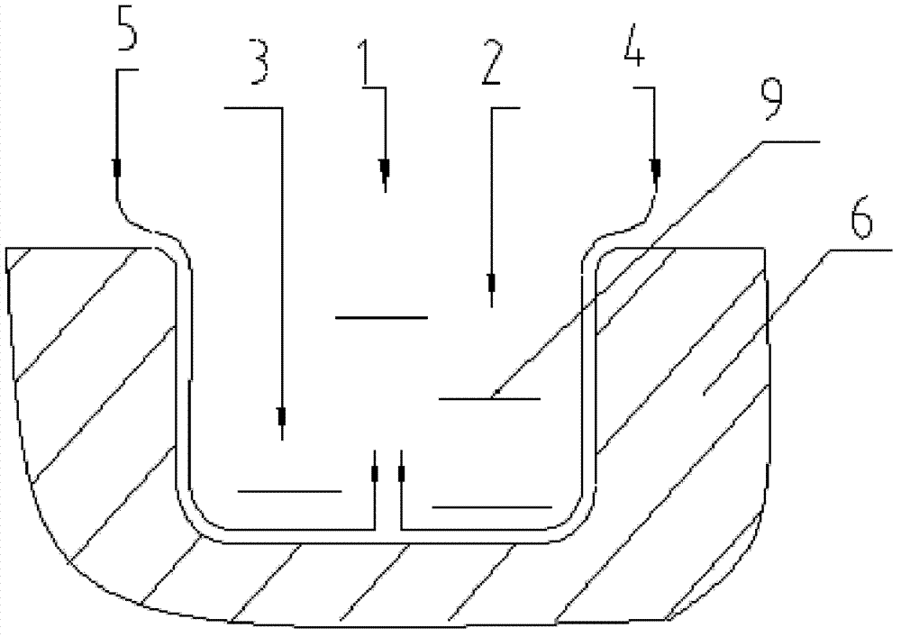
[0021] (3) Rough machining cutting path, the sealing groove 6 is divided into four processing layers 9, the corresponding processing layer 9 is processed with 5 knives, the linear speed is 120m / min, the cutting feed is 0.10mm / r, and the above The cutting speed leaves the part surface; the first to third machining layers (such as figure 1 The processing sequence in 1~3 cuts) occupies 1 / 3 of the groove depth, the fourth processing layer (that is, 4 cuts), and the fi...

Embodiment 2

[0026] A method for processing the roughness of a sealing groove, the steps of which are as follows:

[0027] (1) Selection of groove cutter: choose a groove cutter with a rake angle of 20° and a concave arc-shaped chip breaker, the elongation of the cutter bar is 4mm, and the cutting edge is ground to Ra0.4;

[0028] (2) Clamping: Non-rigid clamping, that is, the parts are clamped by the main shaft without the support of the top or the center frame;

[0029] (3) Rough machining, the sealing groove 6 is divided into four processing layers 9 in depth, and the corresponding processing layer 9 is processed and cut with 5 knives, the line speed is 120m / min, the cutting feed is 0.07mm / r, and the above cutting speed leave the surface of the part;

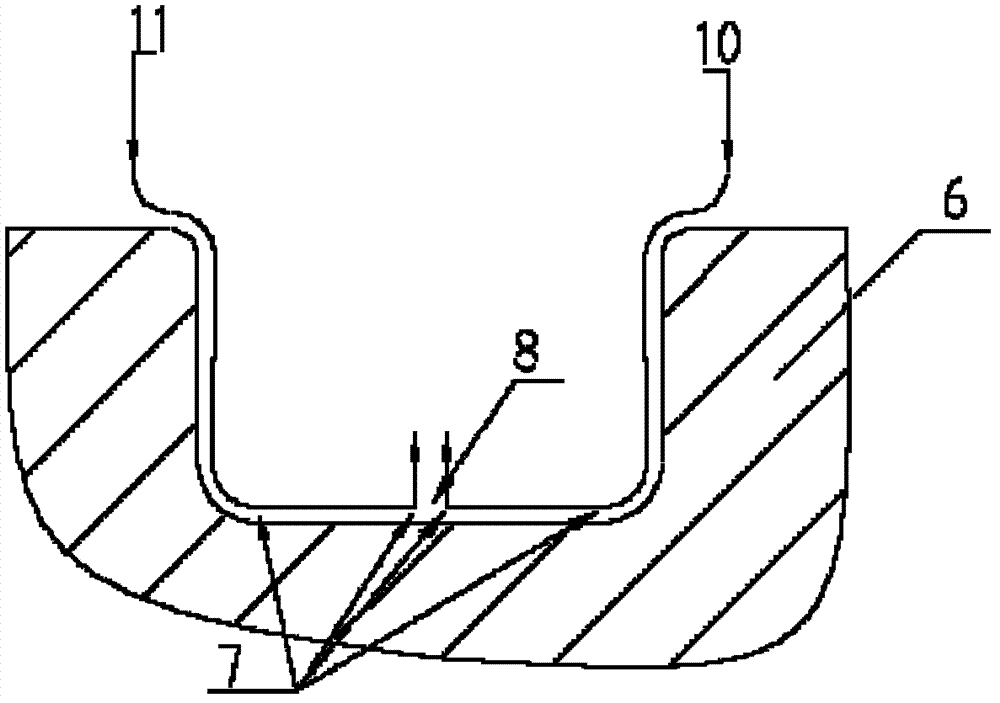
[0030] (4) Finishing, cut into the circular arc on both sides of the sealing groove 6, the linear speed is 120m / min, and the cutting feed is 0.03mm / r; set a cutting pause point 7 on the bottom of the groove bottom arc and the center of t...


PUM


Abstract

The invention relates to a machining method of the roughness of a seal groove. The machining method comprises the following steps of: selecting a slotting cutter with a knifepoint front angle of 15-25 degrees and a concave-arc-shaped chip breaker groove; carrying out rigid clamping; carrying out rough machining; dividing the groove depth of the seal groove into four machining layers; carrying out slitting and layering on the corresponding machining layers and machining and cutting in a linear speed of 100-120m / min and a cutting feeding speed of 0.07-0.15mm / r; carrying out fine machining; and carrying out circular-arc cutting-in at two edges of the seal groove, setting cutting breakpoints on the circular-arc bottom of the groove bottom and the cutting path center of the groove bottom, and cutting according to 2-4s of cutting feeding stop. The machining method disclosed by the invention is convenient and simple to operate; the vibration of the cutter and parts is reduced because a low feeding amount and rapid clamping way is adopted, and thus the machining quality is good; the cutting paths of rough machining and fine machining are adjusted, and thus the roughness of the machined parts of the seal grooves is good; manual polishing is not required, and thus personal factors during machining are reduced; the machining efficiency is increased; and the machining cost is reduced.

Description

technical field [0001] The invention relates to a method for processing a sealing member, in particular to a method for processing the roughness of a sealing groove. Background technique [0002] With the continuous improvement of machining technology, roughness has gradually become one of the main factors affecting product performance and life. Among them, the fluid control system has the most stringent requirements on the roughness of the parts, and in machining, the roughness requirements of the sealing groove are the most difficult to meet. [0003] The sealing groove requires the roughness of the three sides of the groove to be Ra0.4~Ra0.8. This ultra-high roughness brings great challenges to machining. At present, the industry generally adopts the method of mechanical processing to achieve the geometric size, and then manually polishes to improve the roughness. Workers' polishing process steps are cumbersome, and are largely limited by workers' skill level and mood. ...

Claims


Application Information

Patent Timeline
Patent Type & Authority Patents(China)
IPC IPC(8): B23P15/00
Inventor 曹立国杨翔
Owner 中国航发湖南南方宇航工业有限公司
Learn More