Horizontal luffing grab portal crane

A bucket door seat and crane technology, which is applied to cranes and other directions, can solve problems that affect the stability and safety of the driver's operation of the grab, reduce the working efficiency of the whole machine, and unstable operating conditions, etc., to achieve good control, stable operation, and long service life long effect

Inactive Publication Date: 2011-11-02
江苏海隆重机有限公司
View PDF5 Cites 16 Cited by
  • Summary
  • Abstract
  • Description
  • Claims
  • Application Information

AI Technical Summary

Problems solved by technology

In addition, many existing loading and unloading cranes use rack luffing mechanisms, and their luffing speeds are generally 50-60m / min. The unloading capacity of cranes using this luffing mechanism is generally around 300 tons per hour, and the work efficiency is low. The traditional rack luffing mechanism will generate a lot of noise during use, and the impact caused by the large meshing gap of the rack during the increase and decrease process makes the operation unstable
In addition, the speed of the conventional luffing mechanism is a constant speed. Through the four-bar linkage mechanism composed of the trunk bridge, the boom, the large tie rod and the herringbone frame, it is reflected in the speed of the horizontal translation of the grab. In the case of high speed, the speed changes greatly, so the running state of the grab is unstable when it is moving horizontally, which affects the driver's operation and the stability and safety of the grab running, which in turn has a great impact on unloading and wastes resources. At the same time, it also reduces the working efficiency of the whole machine. Therefore, a new technical solution should be provided to solve the above problems

Method used


Image

  • Horizontal luffing grab portal crane
  • Horizontal luffing grab portal crane
  • Horizontal luffing grab portal crane

Examples


Embodiment Construction

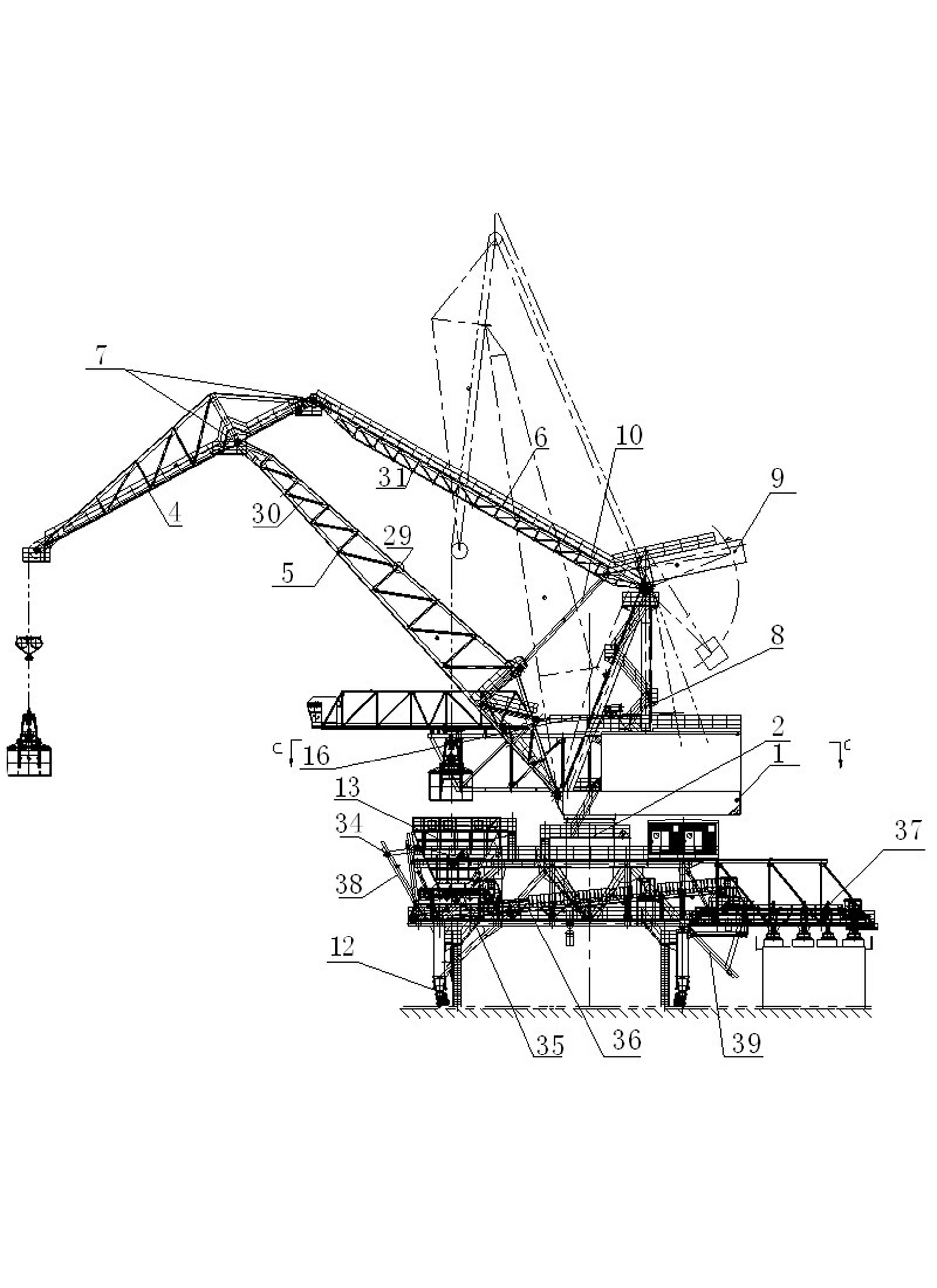
[0018] Such as figure 1 As shown in —5, the horizontal luffing crane with bucket door seat includes a four-link horizontal luffing jib system, an operating mechanism and a mast structure. The tie rod 6 and the herringbone frame 8, the four-link horizontal luffing jib system is fixed on the mast beam 3 through the rotary large bearing ring gear 2 under the swivel frame 1, the elephant trunk bridge 4 of the four-link horizontal luffing jib system 1. The boom 5 and the big pull rod 6 are connected by the hinge shaft 7, the hinge point of the boom 5 root is hinged with the swivel frame 1, the other end of the big pull rod 6 is hinged with the top support of the herringbone frame 8, and the bottom of the herringbone frame 8 is welded on On the swivel frame 1, a counterweight balance beam 9 is also hinged on the head support of the herringbone frame 8, and the counterweight balance beam 9 is hinged with the arm frame 5 through the counterweight pull rod 10. The operating mechanism ...


PUM


Abstract

The invention relates to a horizontal luffing grab portal crane, including a four-bar linkage level luffing boom system, a travelling mechanism and a gantry structure. The crane is characterized in that: a luffing mechanism comprises a triple screw, a screw pedestal and an electric transmission mechanism. The outside of the triple screw is provided with a telescopic cover, the inside of the screw pedestal is equipped with a sleeve with nuts, and two ends outside the sleeve are provided with bearings in the screw pedestal. The electric transmission mechanism comprises a motor, a driving gear and a brake apparatus. The end of the triple screw is hinged to a boom, and the luffing mechanism is equipped with a speed adjustable control system. The four-bar linkage boom system and a gantry beam are both girder construction which employs a T-shaped structure and a rectangular pipe. The T-shaped structure is a main chord member, and the rectangular pipe as a web member is welded on a web member gusset plate. In the blanking process, the T-shaped structure and the web member gusset plate are integrated through numerical control cutting. The crane of the invention has high operating cycle frequency which can reach 6 million times, high luffing speed, smooth running of grab bucket, high operating efficiency and long service life.

Description

technical field [0001] The invention relates to a horizontal luffing crane with a bucket door seat, which belongs to the technical field of major mechanical equipment. Background technique [0002] According to the requirements of domestic crane design specifications, the number of working cycles of general cranes is less than 4 million. The previous domestic cranes of the same type were designed with a box-shaped structure, which generally has a larger windward area. In addition, many existing loading and unloading cranes use rack luffing mechanisms, and their luffing speeds are generally 50-60m / min. The unloading capacity of cranes using this luffing mechanism is generally around 300 tons per hour, and the work efficiency is low. The traditional rack luffing mechanism will generate a lot of noise during use, and the impact caused by the large meshing clearance of the rack during the increase and decrease process makes the operation unstable. In addition, the speed of the...

Claims


Application Information

Patent Timeline
Patent Type & Authority Applications(China)
IPC IPC(8): B66C23/62B66C23/82
Inventor 张浩星程欢吉华
Owner 江苏海隆重机有限公司
Why Eureka
Try Eureka