Hydroelectric end connecting device for rotating target

A terminal connection and rotating target technology, which is applied in the field of hydropower terminal connection devices, can solve problems such as inability to rotate and adjust, unstable connection, complex structure of hydropower terminals, etc., and achieve the effect of reducing disassembly steps and facilitating smooth work

Inactive Publication Date: 2012-12-19
黄峰
View PDF0 Cites 2 Cited by
  • Summary
  • Abstract
  • Description
  • Claims
  • Application Information

AI Technical Summary

Problems solved by technology

[0003] However, the existing hydropower terminal has a complex structure, cannot adapt to the replacement needs of different targets, and cannot perform effective rotation adjustments
In this way, once the target is replaced, the connection is prone to instability, which affects the later maintenance and the coating quality of the product.

Method used


Image

  • Hydroelectric end connecting device for rotating target

Examples


Embodiment Construction

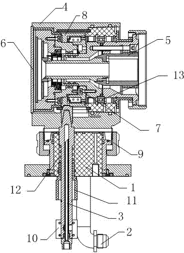
[0014] Such as figure 1 The shown hydroelectric terminal connection device for a rotating target includes a seat core 1, which is different: a water pipe 2 and a conductive rod 3 are respectively installed on the seat core 1 used in the present invention. At the same time, a housing assembly 4 is connected to the seat core 1 , a shaft retaining ring 5 is provided at one end of the housing assembly 4 , and a cover 6 is provided at the other end of the housing assembly 4 . Moreover, a skeleton type oil seal assembly 7 is arranged at the tail end of the shaft retaining ring 5 , and a conductive rod head 8 is sheathed on the periphery of the skeleton type oil seal assembly 7 .

[0015] In view of a preferred embodiment of the present invention, in order to improve the firmness of the whole, a base fitting 9 is provided on the periphery of the seat core 1 . Moreover, in order to facilitate the effective combing of the wire harness and the normal operation of the conductive rod 3 ,...


PUM


Abstract

The invention relates to a hydroelectric end connecting device for a rotating target; and the hydroelectric end connecting device for the rotating target comprises a seat core and is characterized in that a water pipe and an electric-conductive rod are respectively mounted on the seat core and the seat core is connected with a shell module. Moreover, a shaft retainer ring is arranged at one end of the shell module; and a sealing cover is arranged at the other end of the shell module. A framework type oil seal module is arranged at the tail end of the shaft retainer ring. Meanwhile, an electric-conductive rod head is sleeved on the periphery of the framework type oil seal module. Therefore, while a target material is replaced, the assembling and disassembling steps can be effectively reduced. More importantly, the shaft retainer ring is mutually matched with a base closing piece so that the rotation force of the driving can be effectively transmitted to facilitate the smooth working ofthe target material.

Description

technical field [0001] The invention relates to a terminal connection device, in particular to a hydroelectric terminal connection device for a rotating target. Background technique [0002] At present, most of the equipment for producing coated glass adopts planar sputtering cathode target. Its working principle is: the glass to be coated is sent into the vacuum coating chamber, and a certain amount of high-purity process gas such as oxygen, nitrogen or Argon gas, under the action of electromagnetic field and free electrons, the process gas forms positively charged plasma. Under the attraction of the cathode carrying high negative voltage, the plasma bombards the fixed installation according to a certain trajectory and intensity under the control of the magnetic field. The coating material on the planar cathode target in the vacuum coating chamber is collided by gas molecules and deposited on the glass in a certain direction to form a film with a certain thickness. [0003...

Claims


Application Information

Patent Timeline
Patent Type & Authority Patents(China)
IPC IPC(8): C23C14/35
Inventor 黄峰
Owner 黄峰
Why Eureka
Try Eureka