
Closed automatic slag discharge device for boiling chlorination furnace

A boiling chlorination furnace, automatic slagging technology, applied in the direction of fluidized bed furnace, furnace, furnace type, etc., can solve the problems of low reaction efficiency, chlorine gas pollution environment, low utilization rate of chlorine gas, etc., to solve serious environmental pollution, The reaction is complete and the effect of improving the utilization rate of chlorine gas

Active Publication Date: 2011-11-02
INST OF RESOURCES UTILIZATION & RARE EARTH DEV GUANGDONG ACAD OF SCI
View PDF8 Cites 18 Cited by
  • Summary
  • Abstract
  • Description
  • Claims
  • Application Information

AI Technical Summary

Problems solved by technology

[0004] The purpose of the present invention is to address the above-mentioned problems and deficiencies, to provide a method that can solve the serious environmental pollution caused by the leakage of chlorine gas caused by the existing intermittent artificial slagging method and the large change in the bed height of the boiling chlorination furnace before and after slagging. Closed automatic slagging device for fluidized chlorination furnace that leads to problems such as low utilization rate of chlorine gas and low reaction efficiency

Method used

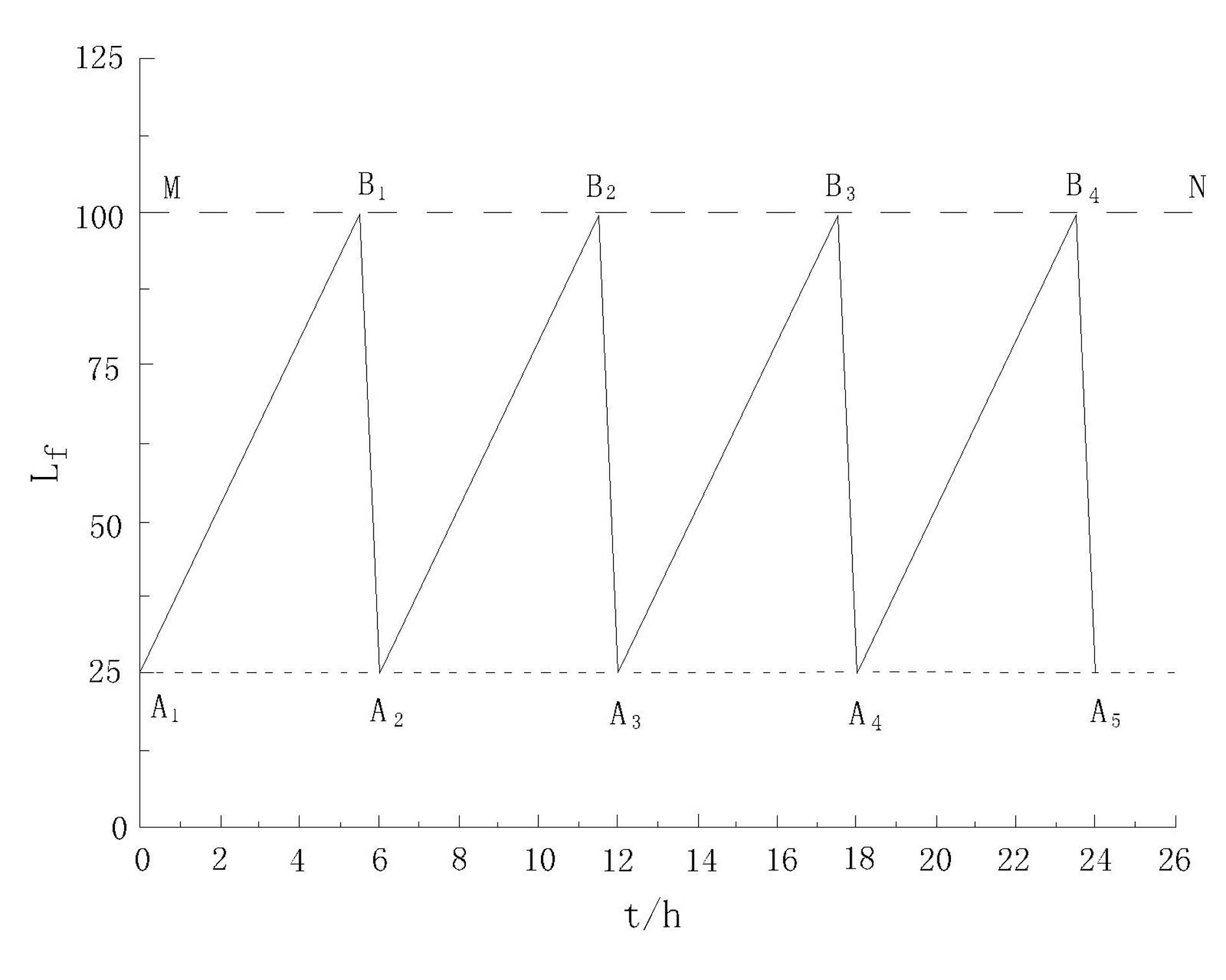

Image

  • Closed automatic slag discharge device for boiling chlorination furnace
  • Closed automatic slag discharge device for boiling chlorination furnace
  • Closed automatic slag discharge device for boiling chlorination furnace

Examples


Embodiment Construction

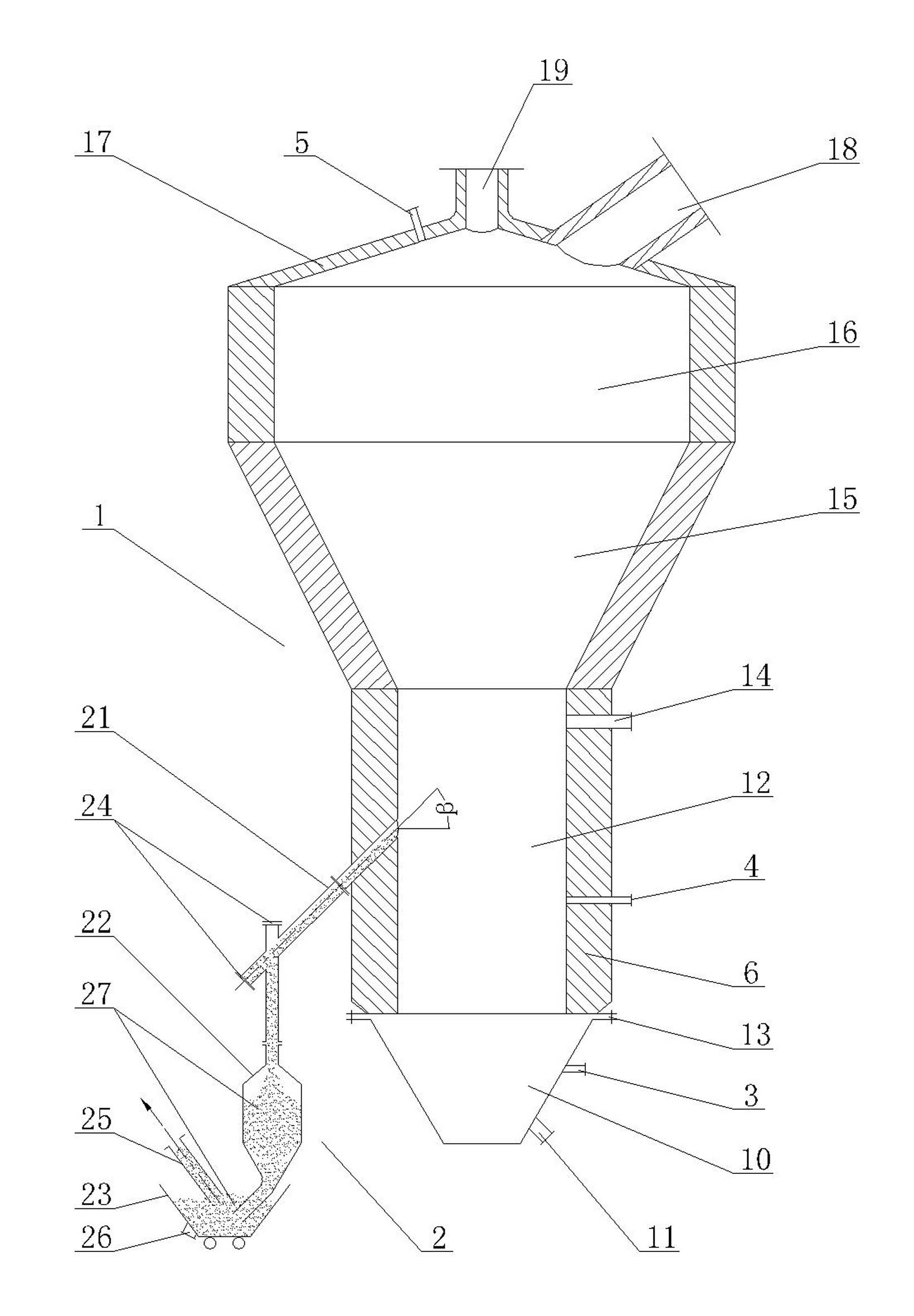
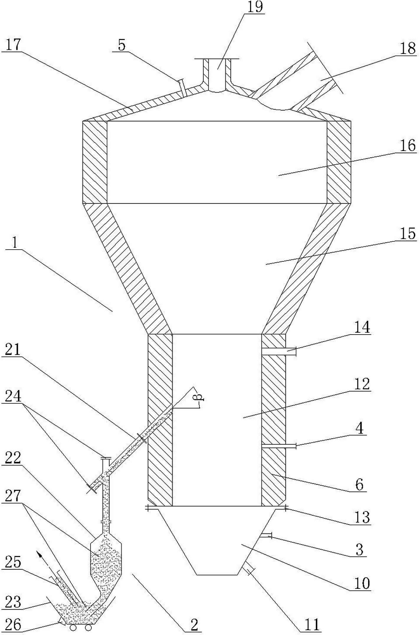
[0015] Such as figure 2 As shown, the closed automatic slagging device of the fluidized chlorination furnace of the present invention comprises a furnace body 1 and a slagging device 2 connected with the furnace body 1, and the slagging device includes a slagging pipe 21, a slag tank 22 and The slag storage hopper 23, wherein the slag discharge pipe 21 is installed on the boiling section 12 of the furnace body inclined downward, and the input port of the slag discharge pipe 21 is connected with the inner cavity of the furnace body, and the output port is connected with the input port of the slag tank 22 The output port of the slag tank 22 is located in the cavity of the slag storage hopper 23. In order to prevent chlorine gas from leaking out during the slag discharge process, the slag discharge device 2 uses a certain amount of slag 27 retained in the slag tank 22 to form the first The first material seal, and the slag 27 automatically discharged into the slag storage hopper...


PUM


Abstract

The invention provides a closed automatic slag discharge device for a boiling chlorination furnace. The slag discharge device comprises a slag discharge tube, a slag tank and a slag storage funnel, wherein the slag discharge tube is slantways arranged on a boiling section of a furnace body downward; the input port of the slag discharge tube is communicated with an inner cavity of the furnace bodyand the output port of the slag discharge tube is communicated with the input port of the slag tank; the output port of the slag tank is formed in a cavity body of the slag storage funnel; and in theslag discharge device, a first material seal is formed through furnace slag retained in the slag tank and a second material seal is formed through furnace slag discharged to the slag storage funnel. The closed automatic slag discharge device can realize closed automatic overflow and continuous slag discharge based on an automatic overflow theory under the condition that the height of a bed layer in the boiling chlorination furnace is in direct proportion to the material quantity and the differential pressure of the bed layer; during slag discharge, the chlorine supply and the material supply are not required to be stopped; in the whole production process, the height of the bed layer of the boiling chlorination furnace is kept stable automatically, so stable and high fluidization quality can be obtained and the chlorine utilization rate can be increased remarkably; moreover, two material seals are formed through the furnace slag in the slag tank and the furnace slag in the slag storagefunnel and the chlorine cannot be leaked, so the working environment and the working condition are improved basically.

Description

technical field [0001] The invention relates to a fluidized chlorination furnace, in particular to a closed automatic slagging device for the fluidized chlorination furnace. Background technique [0002] In the mid-1970s, Guangzhou Institute of Nonferrous Metals researched and developed a new technology of boiling chlorination without sieve plate, which was industrialized in 1979. It replaced the traditional boiling chlorination furnace with sieve plate, and it can not only chlorinate ordinary high-titanium It can also chlorinate the high-titanium slag of Panzhihua Mine containing ∑MgO+CaO as high as 7% to 9%, and has passed the acceptance of Panzhihua Mine Titanium Resources National Key Scientific and Technological Project. Since the fluidized chlorination furnace without sieve plate can operate stably for a long time, it has been used in many titanium factories in my country. However, at present, various manufacturers generally adopt intermittent manual slag removal meth...

Claims


Application Information

Patent Timeline
IPC IPC(8): F27B15/09C22B34/12B01J8/24
Inventor 温旺光王英唐仁衡张峰高远陈怀杰李伟
Owner INST OF RESOURCES UTILIZATION & RARE EARTH DEV GUANGDONG ACAD OF SCI
Learn More