
Design method for double closed loop direct current speed regulation system optimal controller

A technology of DC speed regulation and design method, which is applied in the direction of excitation or armature current control, etc., can solve problems such as calculation result errors, and achieve the effects of reduced calculation errors, fast tracking, and convenient and fast program execution

Inactive Publication Date: 2011-11-02
ANSTEEL GRP MINING CO LTD
View PDF0 Cites 5 Cited by
  • Summary
  • Abstract
  • Description
  • Claims
  • Application Information

AI Technical Summary

Problems solved by technology

But it only has parameter calculation formulas. When debugging the system, if the system performance is not satisfactory, the direction of parameter adjustment cannot be made clear; moreover, some approximations and simplifications are made while ignoring secondary factors during the formation of formulas and charts, which makes the calculation results exist. There is a certain error
For complex situations that cannot be simplified into typical systems, engineering calculation methods are helpless

Method used


Image

  • Design method for double closed loop direct current speed regulation system optimal controller
  • Design method for double closed loop direct current speed regulation system optimal controller
  • Design method for double closed loop direct current speed regulation system optimal controller

Examples


Embodiment Construction

[0031] The specific implementation manner of the present invention will be further described below in conjunction with the accompanying drawings.

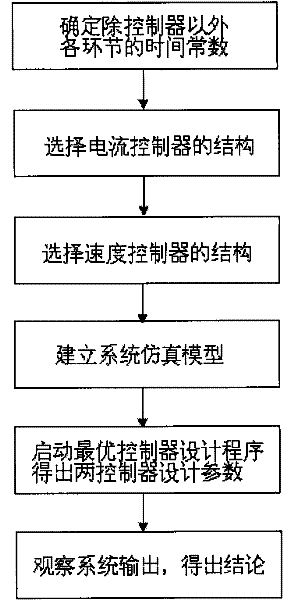
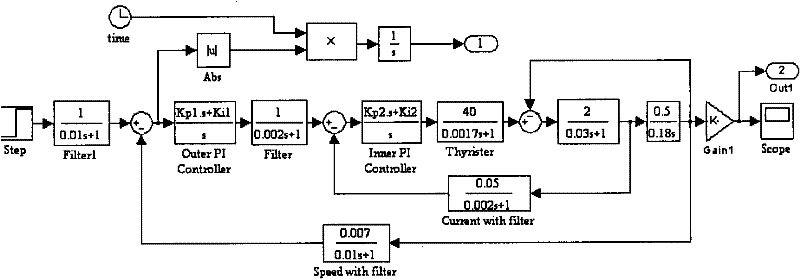
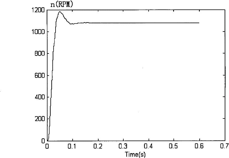
[0032] Such as figure 1 As shown, the design method of the optimal controller of the double-closed-loop DC speed regulation system of the present invention is characterized in that it comprises the following steps:

[0033] 1) First determine the time constants of each link in the double closed-loop system except the controller:

[0034] (1) Rectification device lag time constant T s , for a three-phase bridge rectifier, the average lag time T of the lag time constant of the rectifier s = 0.0017s,

[0035] (2) Current filter time constant T oi , for a three-phase bridge circuit with power frequency on the AC side, the current filter time constant T oi , the time of each wave head is 3.33ms[1s / (50*6)=3.33ms)], in order to basically filter the wave head, there should be (1~2) times T oi =3.33ms, so take T oi = 2ms = 0.002s,

...


PUM


Abstract

The invention is directed to the field of double closed loop direct current speed regulation system technology and particularly relates to a design method for a double closed loop direct current speed regulation system optimal controller. Firstly, the time constants of other links other than the controller are determined. The structure of the controller is selected. An OCD program is adopted so that two string grade controllers of the double closed loop direct current speed regulation system can be simultaneously designed through a computer auxiliary design technology. The parameters of the controllers can be directly obtained through the execution of the program. When the system works, the optimal controller design program starts to operate to directly obtain the parameters of the inner and outer shroud controllers when a JITAE index is optimal. Under a structure of double closed loop of electricity flow and speed, the two controllers control the continuous feedbacks of armature current and speed signal of a motor so that the speed regulation of the motor can be realized. The method surpasses the traditional way that it is a must to design the outer shroud based on the parameters of the inner shroud, the design thinking is more concise and the program execution is convenient and fast. Meanwhile, the calculation error of the system is reduced and the result is more accurate because simplification and approximation in system model derivation are reduced.

Description

technical field [0001] The invention belongs to the technical field of double-closed-loop DC speed regulation systems, and in particular relates to a design method for an optimal controller of a double-closed-loop DC speed regulation system. Background technique [0002] There are two traditional design methods for double-closed-loop DC speed control systems: one is to use the Bode diagram method; the other is to use engineering calculation methods. But both methods have disadvantages. When using the Bode diagram method to design the controller, it is necessary to first obtain the open-loop logarithmic frequency characteristics of the designed closed-loop system, and then determine the expected characteristics of the corrected system according to the performance indicators. After repeated trials, the characteristics of the controller can be determined. , and calculate its parameters. This trial and error process required skilled design skills and was accompanied by a lot o...

Claims


Application Information

Patent Timeline
IPC IPC(8): H02P7/06
Inventor 苍晴高景俊
Owner ANSTEEL GRP MINING CO LTD
Learn More