
Fixture for processing continuous curved surface

A fixture and curved surface technology, applied in the direction of manufacturing tools, metal processing equipment, grinding machine parts, etc., can solve the problems of low machining accuracy, cumbersome operation, and low efficiency, and achieve high machining accuracy, low cost, and simple equipment Effect

Inactive Publication Date: 2011-11-09
BAOSTEEL SPECIAL STEEL CO LTD
View PDF4 Cites 19 Cited by
  • Summary
  • Abstract
  • Description
  • Claims
  • Application Information

AI Technical Summary

Problems solved by technology

Since the surface grinder cannot meet the needs of continuous curved surfaces, it can only be processed by pattern scribing at present, that is, according to the specifications of the chute, a special metal pattern is made in advance, and the pattern is painted on the side of the chute and marked, and then The chute is fixed on the flat-nose pliers on the bed of the surface grinder. According to the marking marks, several continuous curved surfaces composed of these straight lines are manually processed one by one. Each curved surface needs to be measured many times, and the flat is loosened after completion. The pliers readjust the angle of the chute to process the next curved surface until completion
[0006] The above-mentioned "model marking method" processing method: the operation is cumbersome, the efficiency is low, and the processing accuracy is not high, and manual polishing and correction are required to achieve smooth connection of continuous curved surfaces
[0007] In addition to the above-mentioned "model scribing method" processing method, with the continuous improvement of numerical control technology, numerical control processing can also be used to automatically adjust the angle between the tool and the workpiece through the computer to achieve precision processing of continuous curved surfaces. The price of digital processing equipment is too high, which greatly increases the production cost

Method used


Image

  • Fixture for processing continuous curved surface
  • Fixture for processing continuous curved surface
  • Fixture for processing continuous curved surface

Examples


Embodiment Construction

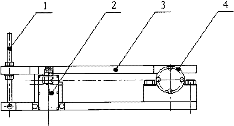
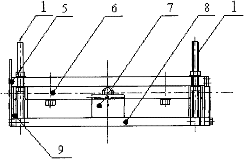
[0053] This embodiment is a typical implementation of the fixture for processing continuous curved surfaces described in the present invention. In this embodiment, the fixture is used in conjunction with a surface grinder.

[0054] like Figure 2a and Figure 2b As shown, the fixture includes a support base plate 8 fixedly arranged horizontally, and two adjustment screw rods 1 are vertically and symmetrically set up at the front and rear parts of the left end of the support base plate 8 respectively. A pair of positioning nuts are provided on the screw 1, which are respectively arranged above and below the panel 3, and play a role in positioning the connection position between the panel 3 and the adjusting screw 1. There is a bearing seat between the right end of the panel 3 and the right end of the supporting base plate 8. 4 and the rotating shaft 6, the bearing seat 4 is fixedly connected with the support base plate 8, and the rotating shaft 6 is fixedly connected with the ...


PUM


Abstract

The invention discloses a fixture for processing a continuous curved surface. The fixture comprises a horizontally fixed bearing bottom plate, at least one adjusting screw rod, a panel and a rotation mechanism; the at least one adjusting screw rod is vertically arranged at the left end of the bearing bottom plate; the lower end of the adjusting screw rod is rotatably connected with the bearing bottom plate; the left end of the panel is connected with the adjusting screw rod which is provided with a pair of positioning nuts arranged above and below the panel respectively; the rotation mechanism is arranged between the right end of the panel and the right end of the bearing bottom plate; and the panel is rotatably connected with the bearing bottom plate through the rotation mechanism. The fixture for processing the continuous curved surface can be matched with multiple kinds of plane processing equipment for using, so that the problem of low accuracy of the continuous curved surface processing in the common plane processing equipment is effectively solved. Moreover, the fixture has low manufacturing cost, and a compact structure, can be assembled and disassembled quickly, and is convenient to use.

Description

technical field [0001] The invention relates to a fixture suitable for machining, in particular to a fixture for machining continuous curved surfaces. Background technique [0002] Grinder refers to a machine tool that uses abrasive tools or abrasives to process various surfaces of workpieces. It is generally used for precision cutting of hardened surfaces of parts. There are many types of grinding machines, and the surface grinder is one of the most common grinding machines, which are mainly used for grinding the plane of the workpiece. [0003] The structure of the surface grinder is relatively complicated, and the processing precision is high. It is a common mechanical processing equipment that grinds the workpiece through the grinding wheel to achieve the required flatness. Its working characteristics are: during the processing, the workpiece is fixed by magnetic force generated by the electromagnetic coil Stand still on the grinding machine bed, let the tool rotate, al...

Claims


Application Information

Patent Timeline
IPC IPC(8): B24B41/00B24B19/02
Inventor 柏永超陈涛蔡斌
Owner BAOSTEEL SPECIAL STEEL CO LTD
Features
  • Generate Ideas
  • Intellectual Property
  • Life Sciences
  • Materials
  • Tech Scout
  • Unparalleled Data Quality
  • Higher Quality Content
  • 60% Fewer Hallucinations
Learn More