Ballast water processing system

A treatment system and ballast water technology, applied in water/sewage treatment, natural water treatment, water/sewage treatment equipment, etc. Reliable destruction or removal of effects

Inactive Publication Date: 2011-11-09
MITSUBISHI SHIPBUILDING CO LTD
View PDF13 Cites 7 Cited by
  • Summary
  • Abstract
  • Description
  • Claims
  • Application Information

AI Technical Summary

Problems solved by technology

[0016] However, general ballast pumps are centrifugal pumps, and the flow rate output from the ballast pump may exceed the treatment capacity of the ballast water treatment device due to the characteristics of the centrifugal pump.
That is, if Figure 5 As shown, the treatment capacity of the ballast water treatment device is, for example, Qm 3 /h, if using the same Qm 3 The centrifugal pump with power corresponding to /h is used as a ballast pump, and the ballast is determined based on the minimum flow rate obtained from the r

Method used


Image

  • Ballast water processing system
  • Ballast water processing system
  • Ballast water processing system

Examples


no. 1 approach 〕

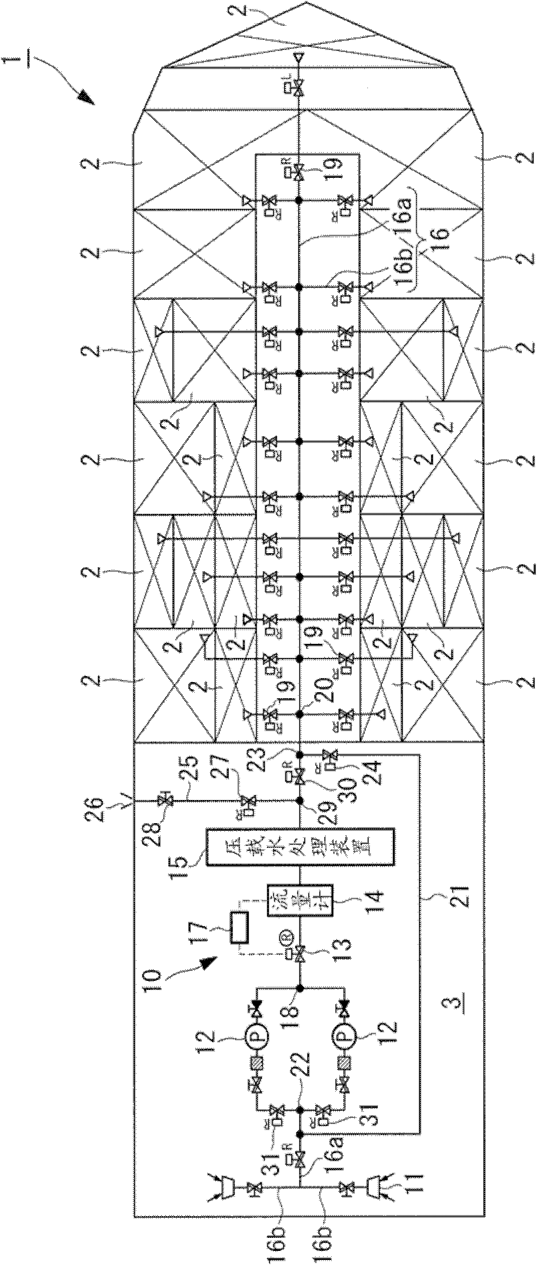
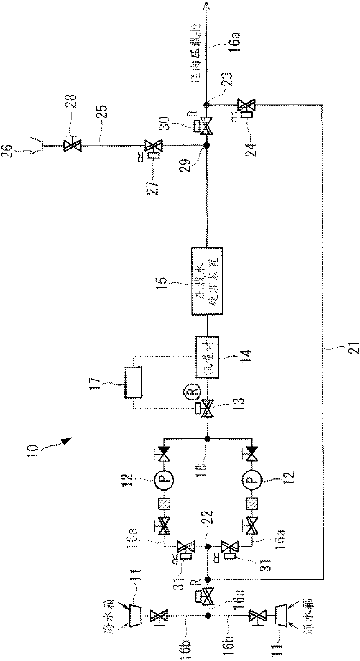
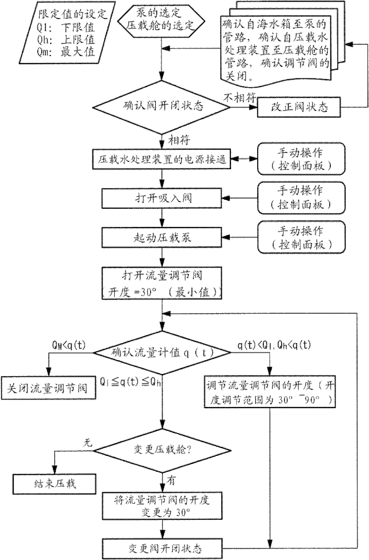
[0065] Below, refer to Figure 1 to Figure 3 A ballast water treatment system according to a first embodiment of the present invention will be described. figure 1 It is a figure which looked at the ship which mounted the ballast water treatment system of this embodiment from above, and is a figure which shows the schematic structure of the ballast water treatment system of this embodiment. figure 2 will be figure 1 Figure showing enlarged representation of the main part. image 3 It is a flowchart for demonstrating the operation procedure of the ballast water treatment system of this embodiment, and the control procedure of a controller.

[0066] The ballast water treatment system of the present invention is mounted on a ship (container ship, LNG ship, oil tanker, etc.) running system.

[0067] The ballast water treatment system 10 of the present embodiment has: a seawater tank (seawater suction port) 11, two ballast pumps 12, a flow regulating (control) valve 13, a flo...

no. 2 approach 〕

[0108] refer to Figure 4 A second embodiment of the ballast water treatment system of the present invention will be described. Figure 4 It is a figure which shows the schematic structure of the ballast water treatment system of this embodiment, and is the same as figure 2 same graph.

[0109] The ballast water treatment system 40 of this embodiment is different from the ballast water treatment system of the above-mentioned first embodiment in that an emergency stop valve 13 ′ is provided instead of the flow control valve 13 , and a bypass line 41 is provided. And bypass valve 42. The other components are the same as those of the above-mentioned first embodiment, and therefore descriptions of these components are omitted here.

[0110] In addition, the same code|symbol is attached|subjected to the same member as said 1st Embodiment.

[0111] The emergency stop valve 13' is a valve whose opening is 0° under the control of the controller 17 when the data measured by the fl...


PUM


Abstract

The invention provides a ballast water processing system and an operation method for the ballast water processing system, which are capable of inhibiting flow outputted from a ballast pump below a processing capability of a ballast water processing device, thereby reliably eliminating or removing aquatic life or bacteria, etc. in the ballast water loaded in a ballast cabin. The ballast water processing system is provided with: a ballast pump (12) outputting the ballast water introduced from a seawater box (11) to a ballast cabin (2); a flow regulating valve (13) increase or decrease flow of the ballast water outputted from the ballast pump (12) via change of openness degree; a flow gauge (14) performing measurement of flow of the ballast water passing by a flow regulating valve (13); a ballast water processing device (15) performing processing of the ballast water passing by the flow gauge (14); and a controller (17) controlling the openness degree of the flow regulating valve (13) in the specified range based on a measurement value measured by the flow gauge (14), to prevent flow of the ballast water supplied to the ballast water processing device (15) be no more than the processing capability of the ballast water processing device (15).

Description

technical field [0001] The present invention relates to a ballast water treatment system capable of exterminating or removing aquatic organisms or bacteria in ballast water loaded in ballast tanks of ships without discharging the treated ballast water adverse effects on the sea. Background technique [0002] Ships for transporting ore, crude oil, etc. are equipped with ballast tanks, and ballast water such as seawater or fresh water is stored in the ballast tanks to control the posture of the hull and ensure stability. Ballast water is introduced into the ballast tank when the ship is empty, and the ballast water is discharged from the ballast tank as loading progresses. Therefore, the ballast water is discharged in a region different from the water intake place. Therefore, the transfer of aquatic organisms, bacteria, etc. with ballast water may cause these aquatic organisms, bacteria, etc. to settle in a new environment, and depending on the situation, there may be damage ...

Claims


Application Information

Patent Timeline
IPC IPC(8): B63B13/00C02F1/50
CPCB63B13/02C02F1/001C02F1/008C02F2103/008C02F2201/005
Inventor 塚本泉大西康介安部和也
Owner MITSUBISHI SHIPBUILDING CO LTD
Why Eureka
Try Eureka