
Solar stove

A technology for solar energy and cooking appliances, applied in the field of cooking appliances, can solve the problems of high energy consumption, high cost, complex structure of multi-functional solar cookers, etc., and achieve the effects of heat preservation and heating speed, low cost and simple structure

Inactive Publication Date: 2011-11-09
上海科伟低压电器厂
View PDF0 Cites 4 Cited by
  • Summary
  • Abstract
  • Description
  • Claims
  • Application Information

AI Technical Summary

Problems solved by technology

The multifunctional solar cooker of the prior art has a complicated structure, high cost and large energy consumption

Method used


Image

  • Solar stove
  • Solar stove

Examples


Embodiment Construction

[0020] According to the claims of the present invention and the contents disclosed in the summary of the invention, the technical solution of the present invention is specifically described as follows.

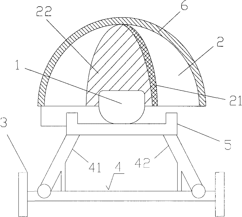
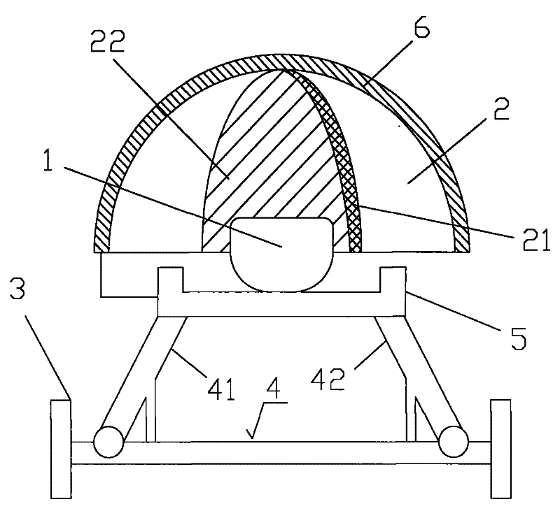
[0021] See figure 1 As shown, the solar cooker of the present invention includes a pot 1, a solar heating cover 2, a base support frame 3, a frame bar 4 and a solar electromagnetic cooker 5; the solar heating cover 2 is a hollow transparent hemispherical structure, and the solar heating cover 2 The cover is placed on the pot 1 for heating the pot 1. The diameter range of the hemispherical solar heating cover 2 is about 0.5-1 meter. The base support frame 3 is placed under the solar heating cover 2. A pair of frames The rod 4 is arranged on the base support frame 3 for placing the pot 1, and the solar electromagnetic cooker 5 is arranged on a pair of frame rods 4 for further heating the pot 1, and a circle is arranged outside the solar heating cover 2 Solar panel 6, the solar ...


PUM


Abstract

The invention relates to a solar stove which comprises a pot, an optical energy heating cover, a base support frame, a pair of rests and a solar electromagnetic oven, wherein the optical energy heating cover is of a hollow transparent semi-spherical structure; the optical energy heating cover covers the pot; the base support frame is placed below the optical energy heating cover; the pair of rests are arranged on the base support frame and are used for placing the pot; the solar electromagnetic oven is arranged on the pair of rests and is used for further heating the pot; a ring of solar-cell panels are arranged outside the optical energy heating cover; and the solar-cell panels can convert sun light energy into heat energy and are connected with the solar electromagnetic oven through conducting wires so as to supply electricity for the solar electromagnetic oven. Because a reflecting film is arranged on the solar stove, the sun light energy is reflected to the pot, and food in the pot is insulated by utilizing the sun light energy; and because the semi-spherical heating cover and the solar electromagnetic oven are arranged, sun light rays are focused on the pot so that heat on the pot is more concentrated, and the heating speed is faster while insulating is achieved.

Description

technical field [0001] The invention relates to a cooker, in particular to a solar cooker. Background technique [0002] At present, a convex lens solar cooker of the prior art has a bracket, a transmission device, a water tank, a convex lens device, a supporting rotating part, a watch mechanical part, an electric transmission device, a water tank heating part, a convex lens device with a convex lens metal frame, and a convex lens The device is installed in the metal bezel, and the convex lens metal bezel is installed on the bracket; the supporting rotating part has a column, which is installed on the base, and a sleeve is installed outside the column, and the watch mechanism has a clock spring, a clock transmission gear, and a transmission gear A cylindrical gear is installed on the shaft, and the cylindrical gear meshes with the clock transmission sleeve gear installed on the upper part of the sleeve; the electric transmission device is composed of a motor, a motor transmi...

Claims


Application Information

Patent Timeline
Patent Type & Authority Applications(China)
IPC IPC(8): F24J2/00F24J2/02F24J2/50F24J2/52F24S20/30H02S40/44
CPCY02B40/18Y02E10/47Y02A40/926Y02E10/50Y02E10/60
Inventor 黄崇园
Owner 上海科伟低压电器厂
Learn More