Liquid observation mirror

A technology of sight glass and mirror body, applied in the field of sight glass, can solve the problems of complicated press-fitting process and high processing cost, and achieve the effects of controlling processing cost, simple structure and improving assembly manufacturability

Active Publication Date: 2015-05-06
ZHEJIANG SANHUA COMMERCIAL REFRIGERATION CONTROLS CO LTD SHAOXING CITY
View PDF8 Cites 1 Cited by
  • Summary
  • Abstract
  • Description
  • Claims
  • Application Information

AI Technical Summary

Problems solved by technology

Obviously, the realization of the above-mentioned fixed relationship has the problems of complicated press-fitting process and high processing cost; at the same time, interference press-fitting will produce internal fluff and impurities

Method used


Image

  • Liquid observation mirror
  • Liquid observation mirror
  • Liquid observation mirror

Examples


Embodiment Construction

[0025] The core of the present invention is to provide a sight glass with an optimized structure. By improving the connection structure between the glass lens and the mirror body, the assembly process can be simplified and the assembly precision can be improved, thereby effectively controlling the processing cost of the product. The present embodiment will be described in detail below in conjunction with the accompanying drawings.

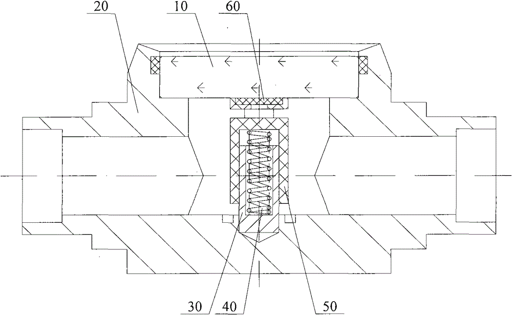
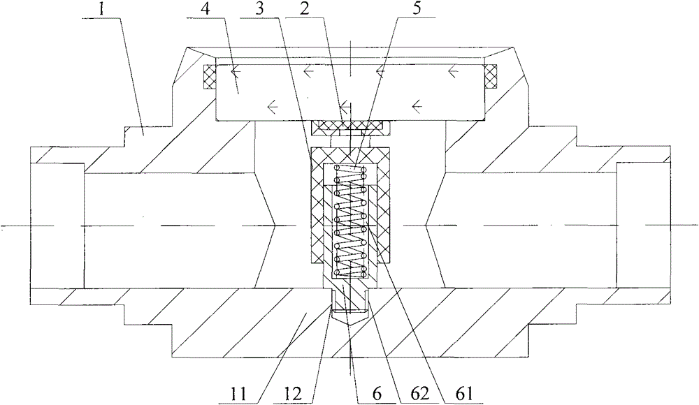
[0026] See figure 2 , which is a schematic diagram of the overall structure of a sight glass.

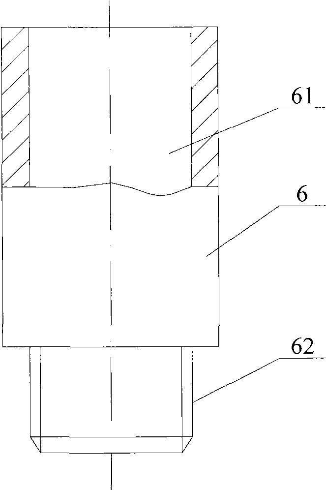
[0027] Such as figure 2 As shown, the sight glass mainly includes a mirror body 1, an indicator 2, an indicator holder 3 for installing the indicator 2, a glass lens 4, a spring 5, a mandrel 6 and other components.

[0028] The mirror body 1 has two interfaces communicating with its internal cavity, which are respectively communicated with the pipeline of the application system, so that the corresponding liquid enters its internal cavity; the indicat...


PUM


Abstract

The invention discloses a liquid observation mirror. The liquid observation mirror comprises a mirror body, an indicator retainer, a central spindle and a spring, wherein the mirror body is provided with an internal chamber as well as a liquid inlet and a liquid outlet which are communicated with the internal chamber, the indicator retainer is arranged in the internal chamber of the mirror body, the central spindle is in threaded connection with the bottom wall of the internal chamber of the mirror body, the upper end face of the central spindle is provided with an axial hole, the spring is inserted in the axial hole of the central spindle, and the upper end face of the spring butts against the indicator retainer. Compared with the prior art, the liquid observation mirror has the advantages of simple and reliable structure since the central spindle is in threaded connection with the mirror body; on the premise of maintaining the stable position relation between the central spindle and the mirror body, the assembly manufacturability is improved greatly, and the production cost of the product is effectively controlled further.

Description

technical field [0001] The invention relates to a refrigeration system monitoring technology, in particular to a sight glass. Background technique [0002] In the existing refrigeration system circuit, the phase change of the refrigerant is mostly used to transfer heat; that is, the refrigerant absorbs heat when it vaporizes in the evaporator, and releases heat when it condenses in the condenser. [0003] During the refrigeration cycle, the water entering the device from the low temperature side is in the state of water vapor, which is compressed together with the refrigerant vapor and enters the condenser, and then condenses into liquid water, which is mixed in the refrigerant liquid in the form of droplets. Obviously, the refrigerant with higher water content directly affects the cooling effect of the system. Even, due to freezing into ice due to low temperature at the expansion valve, the valve is blocked, so that the refrigeration device cannot work normally. [0004] ...

Claims


Application Information

Patent Timeline
Patent Type & Authority Patents(China)
IPC IPC(8): G02B7/02G01N21/78G02B7/00
Inventor 俞志辉
Owner ZHEJIANG SANHUA COMMERCIAL REFRIGERATION CONTROLS CO LTD SHAOXING CITY
Why Eureka
Try Eureka