
Die sole

A base and prototype technology, applied in the field of medical devices, can solve the problems of poor operator level, influence on quality, and unstable quality, and achieve the effects of strong operability and practicability, saving production costs, and improving physical properties

Inactive Publication Date: 2011-11-16
吴树洪
View PDF3 Cites 0 Cited by
  • Summary
  • Abstract
  • Description
  • Claims
  • Application Information

AI Technical Summary

Problems solved by technology

The appearance is more beautiful than the traditional plaster base, but this technology also has the following disadvantages: (1) The processing technology is more complicated, and the operators need professional training; (2) The professional equipment is more expensive, requiring about 60,000-80,000 yuan; (3) The production In the process, special plastic bases and nail implants provided by the manufacturer need to be used. Each set of bases and implant nails is about 6-8 yuan, and the production cost is relatively high; (4) It cannot be prefabricated, and the production cycle of dentures cannot be shortened
However, this technology also has the problem that the process is complicated and the quality is greatly affected by human factors.
The material is still gypsum, which has limited strength and is easily damaged during the process of replacing and wearing, which will affect the quality
[0007] Generally speaking, most of the denture manufacturers in China use the same type of base technology. The main problems are: (1) long production time, many processes, and complicated processes; (2) plaster models are easy to deform and have poor precision; (3) Insufficient base strength and tightness, poor model stability; (4) Unstable quality, poorly affected by the level of operators and other defects
In a word, the currently applied base of the prototype cannot fundamentally solve the problems of high cost, low precision, insufficient stability, and poor practical operability in the production of the existing base of the prototype.

Method used


Image

  • Die sole
  • Die sole
  • Die sole

Examples


Embodiment Construction

[0023] The present invention will be described in further detail below in conjunction with the accompanying drawings and specific embodiments.

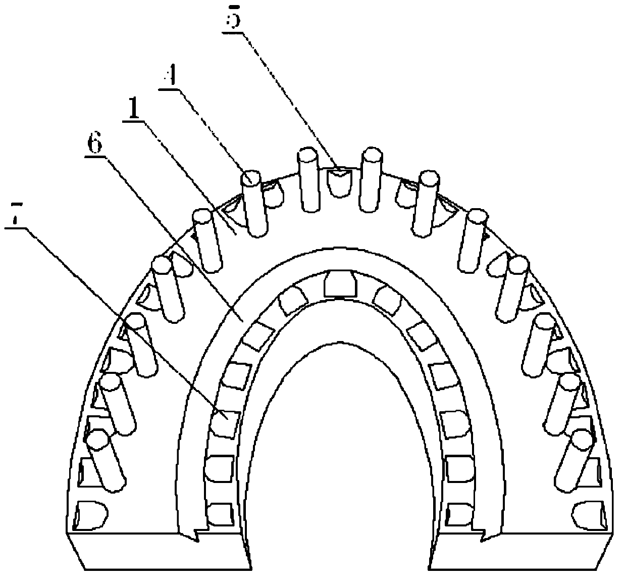
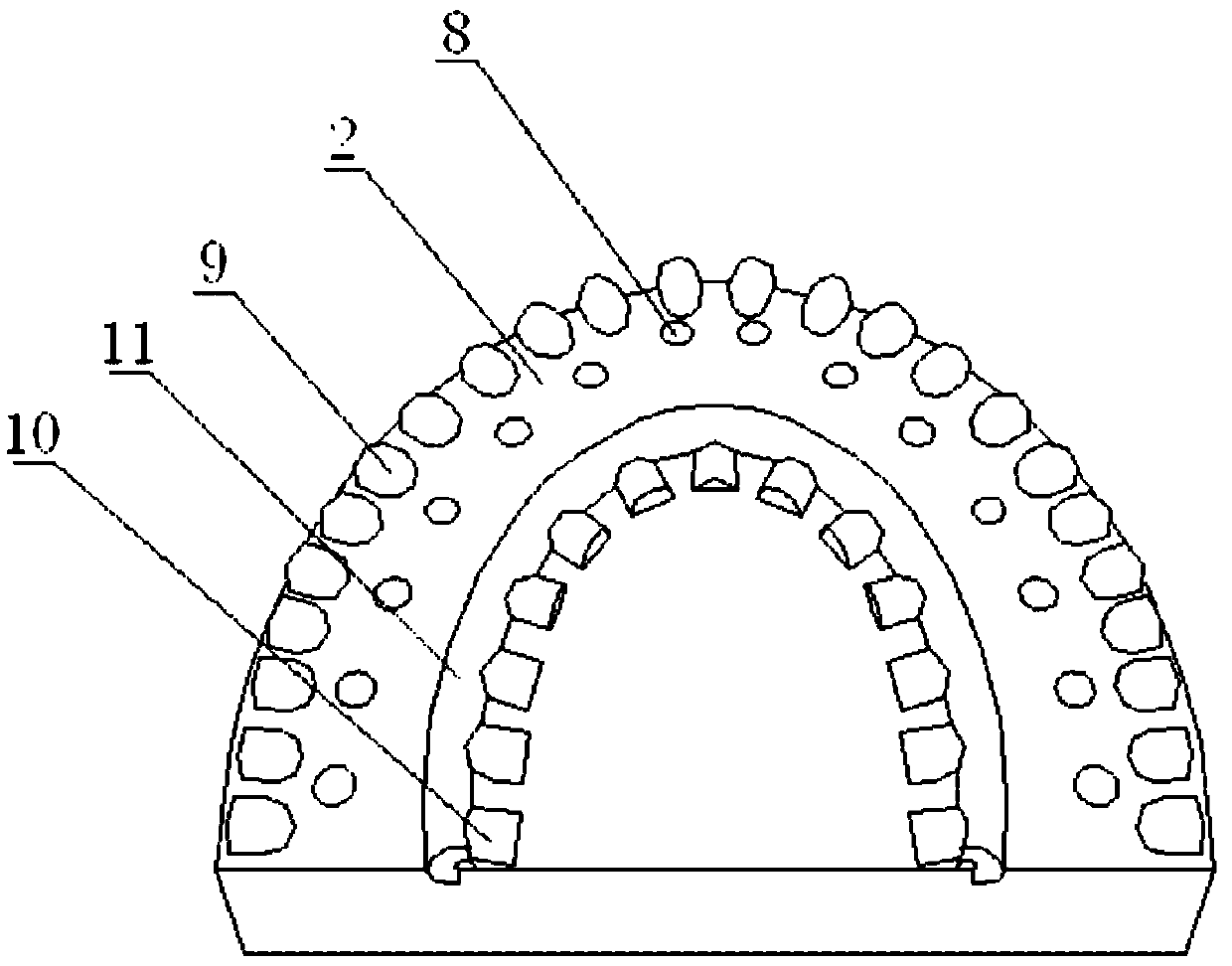
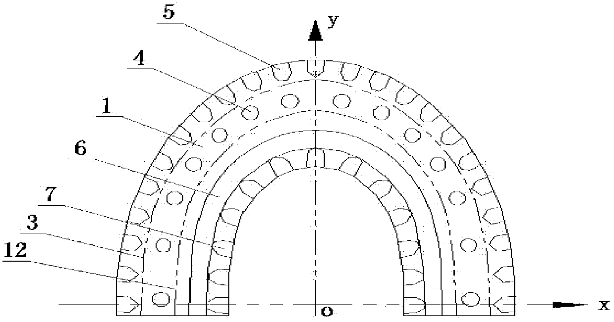
[0024] figure 1 is a schematic diagram of the structure of the substrate, figure 2 is a schematic diagram of the structure of the base, image 3 It is a schematic diagram of the structure of the substrate in the coordinate system, as shown in the figure. The die base includes a substrate 1 made of organic polymers and a base 2 made of organic polymers. Substrate 1 is a horseshoe-shaped structure, and the outer side of substrate 1 is given by Equation 1: The curve 3 drawn above the x-axis is formed by expanding outward by 4-6 mm. The inner edge of substrate 1 is given by Equation 2: The curve 12 drawn above the x-axis is formed by contracting inwardly by 10-12 mm. The base of the substrate 1 is formed by extending 4-6 mm from the x-axis to the negative direction of the y-axis. Between the curve 3 above the x-axis in Equation ...


PUM


Abstract

The invention discloses a die sole comprising a substrate made of an organic polymer and a base, wherein the outer side edge of the substrate is formed by extending from a curve outwards for 4-6mm; the inner side edge of the substrate is formed by contracting from the curve inwards for 10-12mm; the bottom edge of the substrate is formed by downwards extending from an x shaft for 4-6mm; a planting nail is arranged between two curves; the outer side of the planting nail is provided with a first locating slot; the inner side of the planting nail is provided with a locating groove; the inner side of the locating groove is provided with a second locating slot; and the base is provided with a planting nail jack, a first locating lug, a second locating lug and a locating ring. A datum line is drawn by an equation so as to determine the appearance of the die sole. A test proves that the requirements on manufacturing the die sole can be satisfied. The appearance design of the die base is improved or optimized to satisfy the feel of the die beauty of artificial tooth appearance. Meanwhile, manufacturing working procedures are simplified, and influence of uncertain factors on the quality of the die base in the manufacture process is controlled. The die sole can be manufactured in a splitting mode and has the advantages of stronger operability and practicality.

Description

technical field [0001] The invention relates to a medical device, in particular to a die base used in the field of stomatology. Background technique [0002] Die technology is one of the key technologies in the manufacture of fixed dentures. The stability and precision of the base of the die directly affects the quality of the fixed dentures. The traditional production of casts needs to go through the process of model trimming, nailing, plaster base, and splitting the casts. The plaster model needs to be soaked in water repeatedly. Because the plaster absorbs water and expands, it is easy to cause deformation of the manufactured model and affect the quality of the fixed denture. During the production process of fixed dentures, the dies have to be taken and worn repeatedly many times. Since the base is generally made of anhydrite, which is not strong enough, it is easy to cause wear and tear of the mold during repeated removal and wearing, which will cause deformation of the...

Claims


Application Information

Patent Timeline
Patent Type & Authority Applications(China)
IPC IPC(8): A61C13/34
Inventor 吴树洪
Owner 吴树洪
Learn More