Workpiece fixing and rotating device

A technology for rotating devices and workpieces, applied in positioning devices, metal processing machinery parts, clamping, etc., can solve problems such as troublesome operation, affecting workpieces, and failure to meet production needs, etc., to achieve simple structure, reduce labor intensity, and improve work efficiency. efficiency effect

Inactive Publication Date: 2015-03-25
TONGXIANG SHENGHUI PRECISION MACHINERY
View PDF7 Cites 13 Cited by
  • Summary
  • Abstract
  • Description
  • Claims
  • Application Information

AI Technical Summary

Problems solved by technology

[0002] The mechanical workpiece is a single piece that makes up the machine and its inseparability. It plays an important role in the automation industry. The mechanical workpiece includes the connection of parts, the supporting parts, the lubricating lubrication system and the sealing Components, the components of the transmission system that transmit motion and energy, in the process of processing mechanical workpieces, generally use CNC milling machines to finish the mechanical workpieces, and according to the needs of mechanical workpiece processing, they need to be placed on the processing platform The workpiece is rotated so that the milling machine can process the workpiece conveniently. The existing method is generally to rotate the workpiece separately after one side of the workpiece is processed, and the processing platform on which the workpiece is placed does not rotate, so the workpiece is rotated During the process, since there are many workpiece clamping mechanisms on the processing platform, it is necessary to loosen the clamping mechanisms one by one, and use the lifting tool to lift and rotate the workpiece and place it on the processing platform again, and then use the clamping mechanism to lift the workpiece Fixing, the labor intensity of the workers is high, the work efficiency of workpiece processing is low, and in the process of rotating large workpieces, there will often be large deviations in the rotation angle of the workpiece, which will affect the efficient and accurate processing of the workpiece , the existing workpiece rotation device has a complex structure and troublesome operation. It is generally only suitable for processing small workpieces, and it is difficult to fix and rotate larger workpieces. As a result, large workpieces cannot be processed efficiently and accurately, and cannot meet the needs of production.
[0003] The invention patent with application number 200910062924.3 provides a workpiece rotating device, which includes equipment frame, lifting cylinder and mounting plate. The lifting cylinder is connected with the equipment frame through the fixing plate. It is connected to the compression rod through the connecting frame. Rollers are installed at both ends of the compression rod. The rotating cage is located under the mounting plate. The two ends of the rotating cage are connected to the limit guide rail through the rotating shaft. The position of the rollers at both ends of the pressing rod corresponds to the limit guide rail, and the rotating drive device is connected to the rotating shaft through the transmission mechanism. However, the fixing mechanism of the device is single, and it is difficult to efficiently fix workpieces of various specifications, and the workpieces are rotated during rotation. The stability is poor, it is difficult to meet the needs of workpiece processing

Method used


Image

  • Workpiece fixing and rotating device
  • Workpiece fixing and rotating device
  • Workpiece fixing and rotating device

Examples


Embodiment Construction

[0013] In order to further describe the present invention, a specific implementation of a workpiece fixing and rotating device will be further described below in conjunction with the accompanying drawings. The following examples are explanations of the present invention and the present invention is not limited to the following examples.

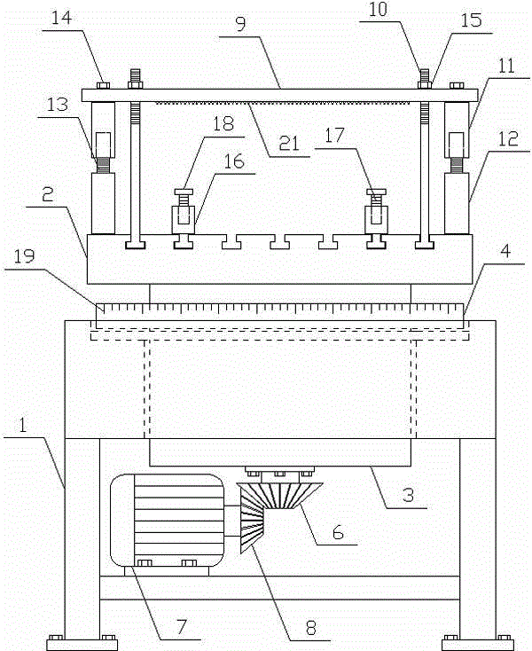
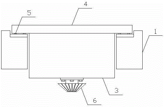
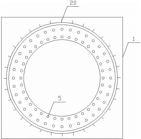
[0014] Such as figure 1 As shown, a workpiece fixing and rotating device of the present invention includes a fixed base 1 and a processing platform 2 , and the processing platform 2 is horizontally arranged on the fixed base 1 . The lower side of the processing platform 2 of the present invention is vertically fixed with a rotating shaft 3, and the outer side of the rotating shaft 3 is horizontally provided with a bearing plate 4, and the fixed base 1 is vertically provided with a through hole matching the rotating shaft 3, and the rotating shaft 3 set vertically in the through hole, such as figure 2 As shown, the upper side of the fixed ba...


PUM


Abstract

The invention discloses a workpiece fixing and rotating device and belongs to the field of machining devices. The workpiece fixing and rotating device comprises a fixed base and a machining platform, wherein the machining platform is horizontally arranged on the fixed base, a rotary shaft is vertically fixed below the machining platform, a bearing plate is horizontally arranged on the outer side of the rotary shaft, multiple balls are evenly arranged between the bearing plate and the fixed base, a main bevel gear is vertically arranged at the output end of a driving motor, an auxiliary bevel gear is meshed with the main bevel gear, multiple through T-shaped grooves are horizontally and evenly formed in the upper side of the machining platform, a compressing mechanism and a lifting mechanism are arranged on the machining platform, the pressing mechanism comprises a pressing plate, a pressing lead screw, a lifting sleeve and a fixing circular truncated cone, and the lifting mechanism comprises a lifting base, a lifting lead screw and a lifting plate. The workpiece fixing and rotating device is simple in structure and capable of rapidly and efficiently fixing a workpiece, accurately rotating the workpiece according to machining requirements and meeting production requirements.

Description

technical field [0001] The invention relates to a rotating device, in particular to a workpiece fixing and rotating device, which belongs to the field of mechanical processing equipment. Background technique [0002] The mechanical workpiece is a single piece that makes up the machine and its inseparability. It plays an important role in the automation industry. The mechanical workpiece includes the connection of parts, the supporting parts, the lubricating lubrication system and the sealing Components, the components of the transmission system that transmit motion and energy, in the process of processing mechanical workpieces, generally use CNC milling machines to finish the mechanical workpieces, and according to the needs of mechanical workpiece processing, they need to be placed on the processing platform The workpiece is rotated so that the milling machine can process the workpiece conveniently. The existing method is generally to rotate the workpiece separately after o...

Claims


Application Information

Patent Timeline
Patent Type & Authority Applications(China)
IPC IPC(8): B23Q3/06B23Q7/00
CPCB23Q3/06B23Q7/00
Inventor 谢欣航
Owner TONGXIANG SHENGHUI PRECISION MACHINERY
Why Eureka
Try Eureka