Tubular centrifuge drum and control method

A separator and drum technology, applied in centrifuges and other directions, can solve the problems that the drum cannot be connected to the power supply, air source or other contact control components, cannot install the rotating weight parts, and it is difficult to close its passage, etc., to achieve Save the purchase of equipment, maintain funds, and improve the effect of service life

Active Publication Date: 2014-04-02
QINGDAO NUOKAIDA MACHINERY MFG
View PDF6 Cites 13 Cited by
  • Summary
  • Abstract
  • Description
  • Claims
  • Application Information

AI Technical Summary

Problems solved by technology

[0004] 1: The high-speed rotation of the drum cannot be connected to power supply, air source or other contact control components, such as carbon brushes, etc.
And due to the strength of the rotor, it is not possible to install revolving parts, such as solenoid valves, etc.
[0005] 2: Due to the high speed, the centrifugal force of the material is very strong, making it difficult to close its passage, and the switching steps must be consistent, otherwise it will cause the rotor to be unbalanced and cause equipment failure
Due to the large force generated by the part in the centrifugal force field, after calculation, a part weighing 6 grams can generate a force of about 10,000 N in the centrifugal force field, making it very difficult to realize this driving force

Method used


Image

  • Tubular centrifuge drum and control method
  • Tubular centrifuge drum and control method
  • Tubular centrifuge drum and control method

Examples


Embodiment Construction

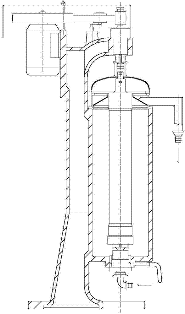
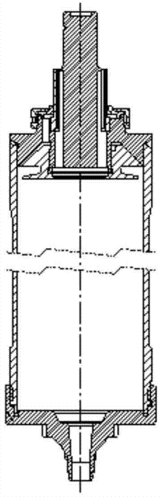
[0054] The tubular separator is a kind of continuous separation and manual slag discharge separation equipment. Due to the limited volume in the cylinder, various devices must be disassembled after the shutdown (see attached figure 1 , Generally, there are locking sleeves, semi-circular sleeves, spindle nuts, liquid pan covers, liquid pans, etc. After the rotor is taken out of the fuselage, the bottom shaft cover is opened to manually clean the sediment in the cylinder. It is an intermittently operated equipment. The drum structure of prior art sees attached figure 2 ; The figure includes a drum 21 and a bottom shaft cover 22 .

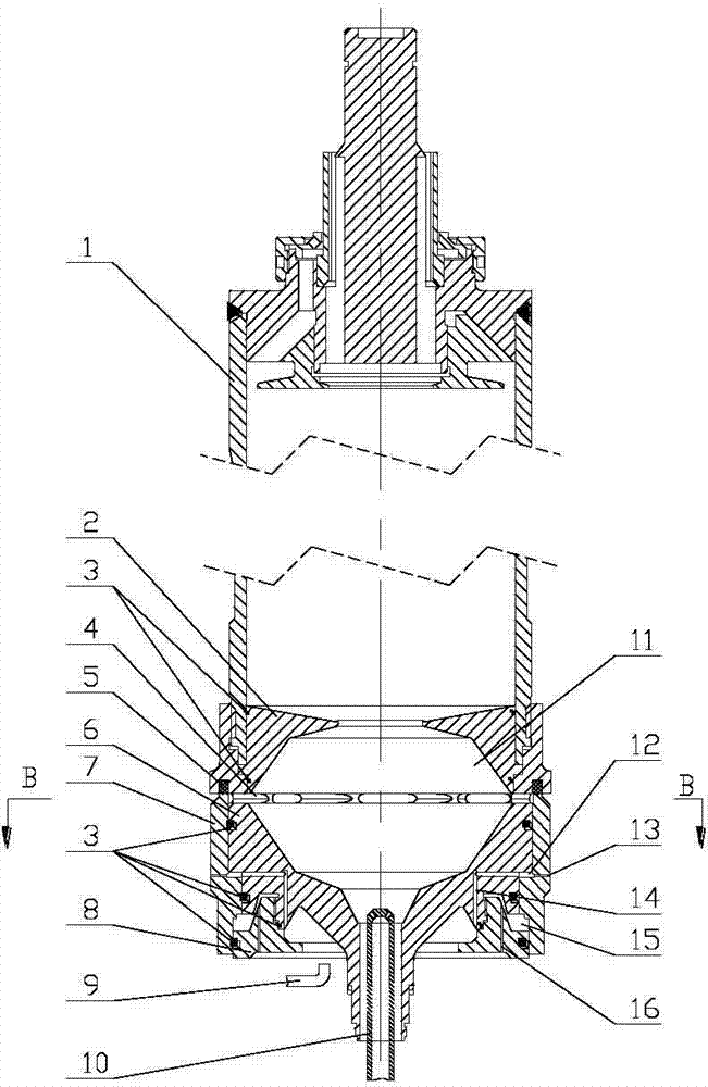
[0055] The present invention has made great improvement on the basis of traditional tubular separator drum (see attached image 3 ), additional hydraulic oil chamber 15, operating water chamber 12 and solid deposition area 11 are added on the original basis. The hydraulic oil chamber 15 has been injected with a certain amount of hydraulic oil in a...


PUM


Abstract

The invention specifically discloses a tubular centrifuge drum and a control method. The tubular centrifuge drum comprises a drum barrel and a bottom shaft cover, wherein a liquid outlet is formed in the upper part of the drum barrel; a blocking disc which is matched with the bottom of the drum barrel is arranged on the bottom of the drum barrel; an opening is formed in the bottom of the blocking disc; the bottom shaft cover is arranged below the blocking disc; a slag discharging hole is formed between the blocking disc and the bottom shaft cover; a ring valve capable of vertically moving is arranged on the outer ring of the bottom shaft cover; a liquid receiving concave ring is arranged on the bottom end face of the bottom shaft cover; a hydraulic oil cavity is formed between the liquid receiving concave ring and the ring valve; an annular space is formed after the ring valve and the bottom shaft cover are mounted, and is used as an operating water cavity; a drain hole is formed in the ring valve; a feeding nozzle is inserted in the bottom of the bottom shaft cover along the axis direction. The working principle of a tubular centrifuge is changed from the modes of continuous separation, halt and manual slag discharging to the modes of continuous separation and automatic slag discharging, halt is not needed during slag discharging, the working rotating speed is not reduced, the feeding does not stop, and the working efficiency is greatly improved.

Description

[0001] technical field [0002] The invention specifically discloses a tubular separator drum and a control method. Background technique [0003] The tubular separator is currently on the market among industrial centrifuges with the highest speed and the highest separation factor. It can also be said to be the model with the best separation effect. Separation of liquid phase-light liquid phase-solid phase. However, due to the drum of the tubular separator, the drum is the core component of the tubular separator. It is generally composed of a thin and long hollow pipe. The material is separated inside it and cannot automatically discharge the slag, and it needs to be manually stopped for cleaning. The disadvantages limit its development and application range, which not only makes the users who use the machine feel inconvenient in operation, especially for some materials with high solid content, due to the small volume of the drum, the solid phase will be in a short time. It...

Claims


Application Information

Patent Timeline
Patent Type & Authority Applications(China)
IPC IPC(8): B04B7/08B04B13/00
Inventor 田忠庆
Owner QINGDAO NUOKAIDA MACHINERY MFG
Why Eureka
Try Eureka