Method and device for controlling power supplying voltage of power consumption device in emitting passage and emitting system

A technology of transmission path and power supply voltage, which is applied in the field of communication and can solve the problems of high power consumption of transmission path and so on.

Active Publication Date: 2011-11-16
北京万海云科技有限公司
View PDF4 Cites 8 Cited by
  • Summary
  • Abstract
  • Description
  • Claims
  • Application Information

AI Technical Summary

Problems solved by technology

[0020] Embodiments of the present invention provide a method and device for controlling the power supply voltage of power consumption devices in the transmission path, and a transmission system, which solves the problem in the prior

Method used


Image

  • Method and device for controlling power supplying voltage of power consumption device in emitting passage and emitting system
  • Method and device for controlling power supplying voltage of power consumption device in emitting passage and emitting system
  • Method and device for controlling power supplying voltage of power consumption device in emitting passage and emitting system

Examples


Embodiment 1

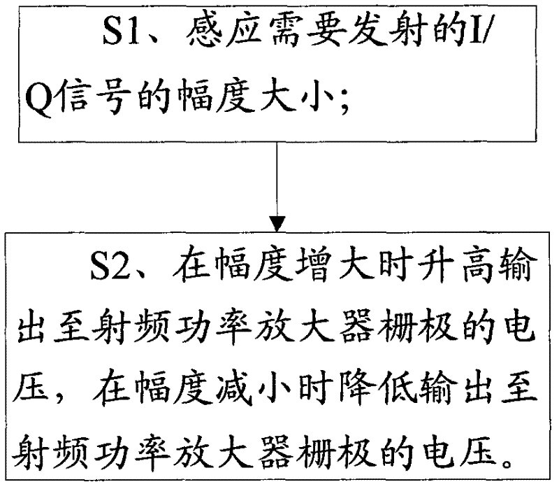
[0129] like image 3 As shown, the method for controlling the power supply voltage of the power consumption device in the transmission path provided by the embodiment of the present invention includes the following steps:

[0130] S1. Sensing the magnitude of the I / Q signal to be transmitted;

[0131] S2. Increase the voltage output to the grid of the radio frequency power amplifier for amplifying the power of the radio frequency signal when the amplitude increases, and decrease the voltage output to the grid of the radio frequency power amplifier when the amplitude decreases.

[0132] Because in the embodiment of the present invention, the amplitude of the I / Q signal that needs to be transmitted can be sensed first, and then the voltage output to the gate of the RF power amplifier for amplifying the power of the RF signal is increased when the amplitude increases, and decreased when the amplitude decreases. The voltage output to the gate of the radio frequency power amplifie...

Embodiment 2

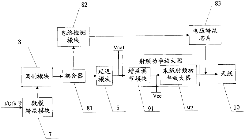
[0215] like Figure 7 As shown, Embodiment 2 of the method of the present invention is basically the same as Embodiment 1 provided by the present invention above, and the difference is that step S1 in this embodiment is: sensing the amplitude of the radio frequency signal after the digital-to-analog conversion of the I / Q signal size.

[0216] In the same way as Embodiment 1 of the method of the present invention, in the embodiment of the present invention, the amplitude of the radio frequency signal after the digital-to-analog conversion of the I / Q signal can be sensed first, and then output to at least one radio frequency power amplifier (such as the final radio frequency power amplifier) ​​according to the amplitude in real time. level RF power amplifier) ​​grid voltage, it can be seen that step S1 in the second embodiment of the method of the present invention and step S1 in the embodiment 1 provided by the present invention are corresponding specific technical features, be...


PUM


Abstract

The embodiment of the invention provides a method and device for controlling power supplying voltage of a power consumption device in an emitting passage and an emitting system, relating to the technical field of communication and solving the technical problem that the power consumption of an emitting passage in the prior art is higher. The method for controlling power supplying voltage of the power consumption device in the emitting passage comprises the steps of: sensing the amplitude of the I/O signals to be emitted or sensing the amplitude of the radio frequency signals which are obtained by carrying out digital-to-analog conversion on the I/O signals; and boosting the voltage output to a grid of a radio frequency power amplifier for amplifying the radio frequency signal power when the amplitude is enlarged and reducing the voltage which is output to the radio frequency power amplifier when the amplitude is reduced. The device for controlling the power supplying voltage of the power consumption device in the emitting passage comprises a sensing module and a controlling module. The emitting system comprises the emitting passage and the device for controlling the power supplying voltage of the power consumption device in the emitting passage, disclosed by the invention. The method and device disclosed by the invention are used for reducing power consumption brought about by the emitting passage part of the complete unit.

Description

technical field [0001] The present invention relates to the field of communication technology, in particular to a method for controlling the power supply voltage of a power consumption device in a transmission path, a device for controlling the power supply voltage of a power consumption device in a transmission path, and a method for setting the power supply voltage of a power consumption device in a transmission path for controlling The launch system of the device. Background technique [0002] With the rapid development of communication technologies, TDD (Time Division Duplexing, time division duplexing) and FDD (Frequency Division Duplexing, frequency division duplexing) technologies have been widely used in communication systems. [0003] The existing communication system includes a transmission path and a reception path. The transmission path is used to transmit wireless signals to the reception path through the power consumption device in it, and the reception path is...

Claims


Application Information

Patent Timeline
IPC IPC(8): H03F3/21
Inventor 王博闻柴旭荣王忠勇
Owner 北京万海云科技有限公司
Why Eureka
Try Eureka