Method for producing an external synchronizer ring

An external synchronization, ring body technology, applied in the direction of gear transmission mechanism, metal processing equipment, clutch, etc., can solve problems such as consumption

Active Publication Date: 2014-12-31
HOERBIGER ANTRIEBSTECHN HLDG
View PDF10 Cites 0 Cited by
  • Summary
  • Abstract
  • Description
  • Claims
  • Application Information

AI Technical Summary

Problems solved by technology

[0004] Joining the friction coating film on the frusto-conical substrate is a complex process

Method used


Image

  • Method for producing an external synchronizer ring
  • Method for producing an external synchronizer ring

Examples


Embodiment Construction

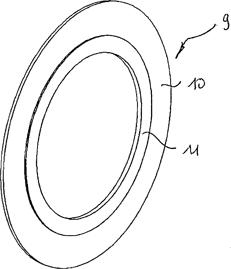
[0024] exist figure 1 shows a pre-punched flat blank 9 having an outer annular first area region 10 and an inner annular second area region 11 adjoining the first area region, thus overall having a smooth outer edge ring.

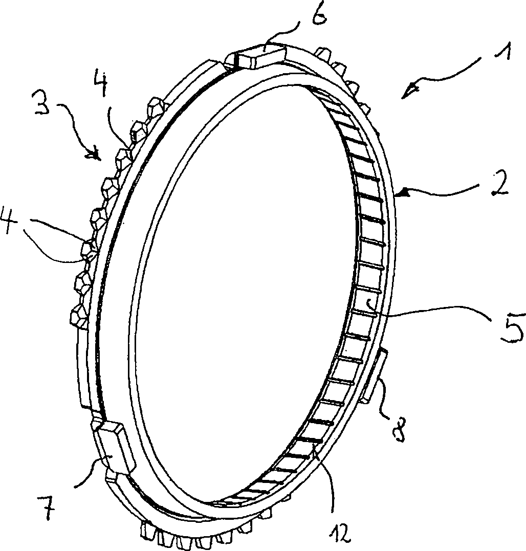
[0025] In this case, the outer area region 10 is designed to form a figure 2 The outer tooth portion 3 with the roof-like slope 4 and the indicator protrusions 6, 7, 8 seen in the figure are arranged on the outer circumference of the conical ring body 2 of the outer synchronous ring 1, as can be obtained by figure 2 See in detail.

[0026] as in figure 2 It can be seen in the figure that the roof slope 4 is a radial surface which is inclined in the axial direction and points in the direction of the axial end of the ring body 2 which is not formed with the external toothing 3 (according to figure 2 The axial end on the right side of the ).

[0027] as in figure 2 As shown in , the ring body 2 can be provided with a diffusion sintered coating 5 a...


PUM


Abstract

#CMT# # / CMT# The method involves pre-stamping a flat blank (9), covering an outer annular surface area (10) of a ring body, and sintering an inner annular surface area (11) of the ring body to form a sintered coating. Another sintered inner surface area is formed into a conical shape, where an external gearing is pre-stamped and index tabs are bent. #CMT#USE : # / CMT# Method for producing an external synchronizer ring. #CMT#ADVANTAGE : # / CMT# The method involves pre-stamping a flat blank, covering an outer annular surface area of a ring body, and sintering an inner annular surface area of the ring body to form a sintered coating, and hence increases technical quality of external synchronizer ring. #CMT#DESCRIPTION OF DRAWINGS : # / CMT# The drawing shows a perspective view of a flat blank. 9 : Flat blank 10 : Outer annular surface area 11 : Inner annular surface area.

Description

technical field [0001] The invention relates to a method for producing an outer synchronizer ring. Background technique [0002] Outer synchronizer rings provided with friction coatings or friction surfaces are usually sintered, forged or deformed from sheet metal. In a subsequent processing step, the friction surface is processed and / or a metallic, organic or carbon-containing friction coating is introduced in a materially or form-fitting manner. The introduction of metallic friction surfaces by means of galvanic or thermal methods is likewise known. [0003] An example of a cohesive connection for a sintered friction coating and a friction surface in an outer synchronizer ring is disclosed in WO 2006 / 004343. [0004] Bonding the friction coating foil to the frustoconical base body is a complex process. In particular, the fastening and dimensionally stable pressing of the coating roll or the layered section within the conical ring can be achieved with relatively little e...

Claims


Application Information

Patent Timeline
Patent Type & Authority Patents(China)
IPC IPC(8): B23P15/00F16D23/02B21D53/16
CPCB21D53/16F16D23/025B23P15/00F16D2250/00
Inventor 彼得·埃希特勒沃纳·菲尔古特
Owner HOERBIGER ANTRIEBSTECHN HLDG
Why Eureka
Try Eureka