Rectifier module with cooled busbar

A technology for power converters and busbar systems, which is applied to output power conversion devices, conversion of AC power input to DC power output, cooling/ventilation/heating transformation, etc., and can solve the problem of increasing busbar system, increasing weight, and increasing costs, etc. question

CN102246612AActive Publication Date: 2011-11-16SIEMENS AG
4 Cites 7 Cited by

Patent Information

Authority / Receiving Office
CN · China
Patent Type
Applications(China)
Current Assignee / Owner
Publication Date
2011-11-16

Smart Images

  • Figure 1
    Figure 1
  • Figure 2
    Figure 2
  • Figure 3
    Figure 3
Patent Text Reader

Abstract

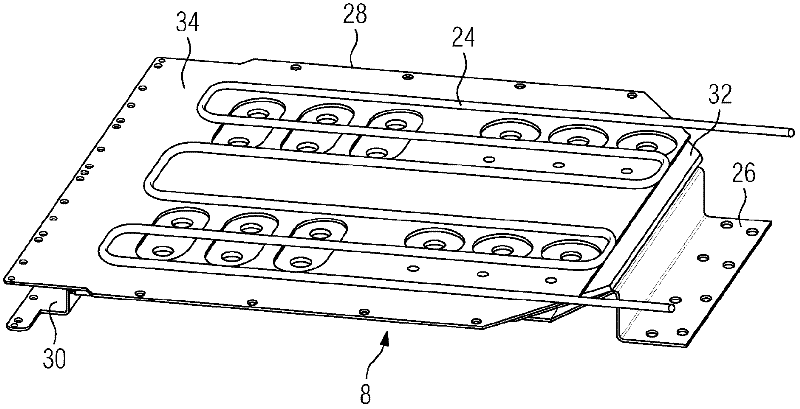
The invention relates to a rectifier module with at least two power semiconductor modules (2, 4), mechanically connected to a fluid cooling body (6) in a thermally-conducting manner and electrically-connected to connectors on the rectifier module by means of a busbar (8) with a least two mutually-insulated conductor tracks. According to the invention, said busbar (8) is connected to a least one coolant line (24), said busbar (8) and said coolant line (24) forming a module. Additional power loss in the laminated busbar (8) is avoided by means of said coolant line (24).
Need to check novelty before this filing date? Find Prior Art

Description

technical field

[0001] The invention relates to a power converter module according to the preamble of claim 1 . Background technique

[0002] General type power converter modules, especially higher power general type power converter modules are commercially available. The power semiconductor modules of this type of power converter module, in particular the switchable power semiconductor modules, are connected to the connection terminals of the power converter module via a low-inductance busbar system. For this purpose, the busbars used must be implemented as planar busbars and stacked on top of each other to form a busbar stack. A plane insulating layer is provided between every two plane busbars. These insulating layers protrude beyond the flat busbars in order to meet the limit values ​​for air gaps and creepage paths. Thus, a low-inductance busbar system of the type described above has at least two busbars and at least one insulating layer. In order to make the busbar...

Examples

Embodiment Construction

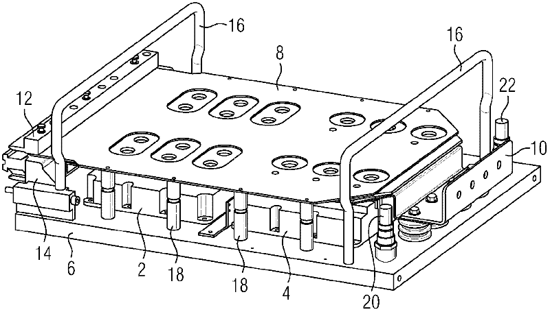
[0017] figure 1 It is a perspective view of a commercially available power converter module, wherein 2 and 4 each represent a power semiconductor module, especially a power semiconductor module that can be turned off, such as an insulated gate bipolar transistor (IGBT), and 6 represents a liquid-cooled radiator , 8 represents the busbar system, 10 represents the load connection terminal, 12 and 14 represent a DC voltage connection terminal, 16 represents the bow-shaped element, and 18 represents the support element. In addition, a coolant inlet 20 and a coolant outlet 22 are shown.

[0018] The two power semiconductor modules 2 and 4 are mechanically fixed together with the liquid-cooled radiator 6 in a detachable manner. The busbar system 8 may have two busbars, such as a positive busbar plus a load busbar, or a load busbar plus a negative pole busbar, or three busbars, such as a positive pole busbar, a load busbar plus a negative pole busbar. The number of bus bars of the ...