Multidirectional discharging method of mobile discharging car

A technology of unloading trolley and unloading roller, which is applied in loading/unloading, conveyor objects, conveyors, etc., can solve the problems of increased maintenance costs, increased equipment procurement costs, and increased equipment height, and can reduce the amount of maintenance and replacement. , The effect of enlarged maintenance space and convenient maintenance

Inactive Publication Date: 2011-11-23
WISDRI ENG & RES INC LTD
View PDF9 Cites 17 Cited by
  • Summary
  • Abstract
  • Description
  • Claims
  • Application Information

AI Technical Summary

Problems solved by technology

Due to the increase of material transportation volume and belt speed, the damage rate of the chute on the unloading vehicle and the flap of the three-way distributor during material transportation is greatly increased, which increases maintenance costs and affects normal production.
Although the internal structure of the chute and the form of the three-way flap have been improved, the damage rate cannot be effectively improved
[0003] When the distance between the unloading points on both sides of the unloading trolley and the center of the unloading trolley increases, the overall equipment height of the unloading trolley needs to be increased, and the length of the equipment needs to be lengthened, which will eventually lead to an increase in equipment weight and equipment purchase costs.
At the same time, due to the increase in the size of the unloading trolley, the required installation space in the factory building will increase.
During equipment maintenance, equipment parts are not easy to disassemble and replace, which increases the difficulty of maintenance. When the equipment installation space is limited, the inclination angle of the blanking chute is too large, which is prone to aggregate material blocking and affects normal production

Method used


Image

  • Multidirectional discharging method of mobile discharging car
  • Multidirectional discharging method of mobile discharging car
  • Multidirectional discharging method of mobile discharging car

Examples


Embodiment 1

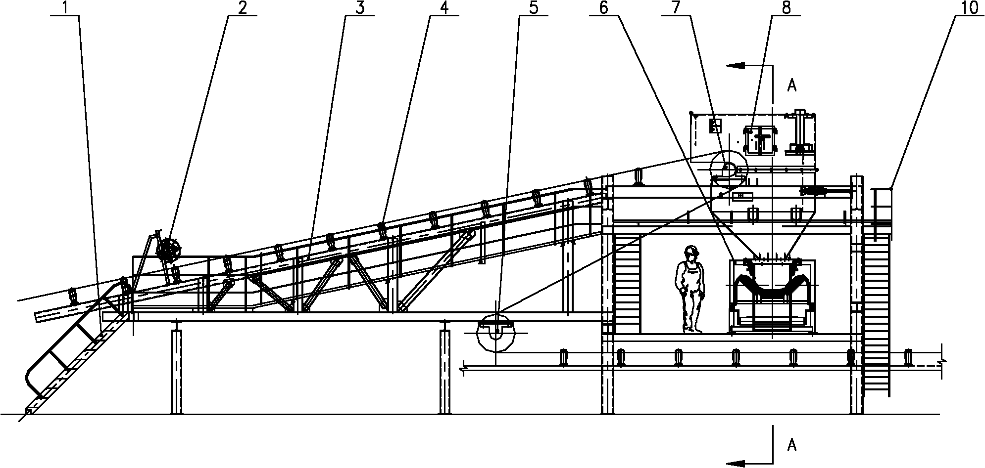
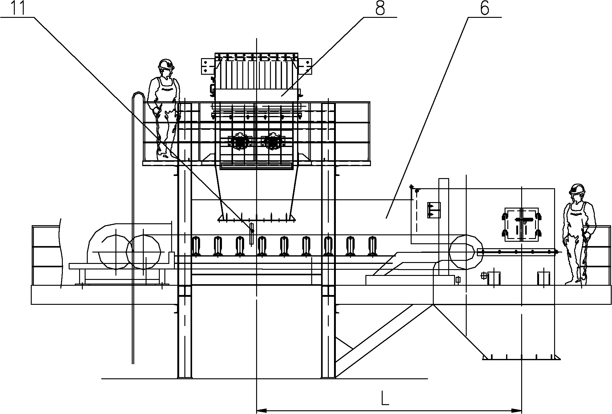
[0030] see figure 1 , 2 , the multi-directional unloading method of the mobile unloading trolley shown in 5, the unloading trolley used includes a ladder 1, a pressure pulley 2, a vehicle frame 3, a trough idler group 4, a redirection drum 5, a belt conveyor Machine 6, head unloading drum 7, funnel 8, maintenance platform 10, anti-belt deviation device 11, centralized lubrication device, funnel shield 13; funnel shield 13 is located above the funnel 8 and surrounds the funnel 8 from around the funnel 8, The upper periphery of the funnel 8 is provided with an inspection platform 10; it is characterized in that: a belt conveyor 6 is arranged along the front and rear directions below the outlet of the funnel 8, and the horizontal distance between the discharge point of the belt conveyor 6 and the outlet of the funnel 8 can be adjusted without increasing The overall height of the conveyor equipment; the anti-belt deviation device 11 is located below the outlet of the funnel 8 cor...

Embodiment 2

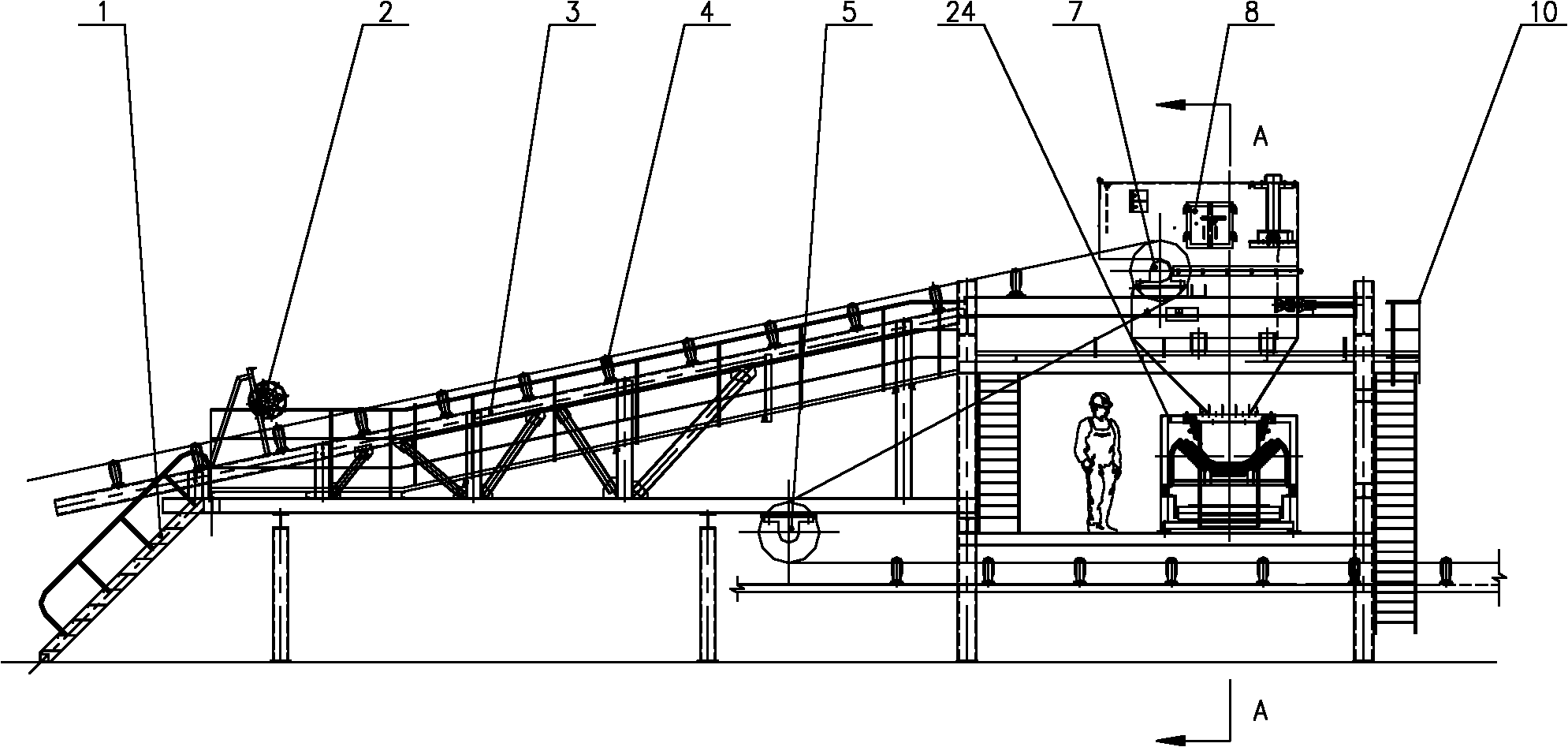
[0039] see image 3 , 4 , the multi-directional unloading method of the mobile unloading trolley shown in 5, the unloading trolley used includes a ladder 1, a pressure pulley 2, a vehicle frame 3, a trough idler group 4, a reversing roller 5, a reversible belt type Conveyor 24, head unloading drum 7, funnel 8, maintenance platform 10, anti-belt deviation device 11, centralized lubrication device, funnel shield 13; funnel shield 13 is located above the funnel 8 and surrounds the funnel 8 from around the funnel 8 , the upper periphery of the funnel 8 is provided with an inspection platform 10; the outlet of the funnel 8 is provided with a reversible belt conveyor 24 along the front and rear directions, and the discharge points at both ends of the reversible belt conveyor are symmetrically or asymmetrically located on the front and rear sides of the funnel outlet. The front and back horizontal distance between the side discharge point and the outlet of the funnel can be adjusted...

Embodiment 3

[0048] see Figure 6-9 In the multi-directional unloading method of the mobile unloading trolley shown, the unloading trolley used includes a ladder 1, a pressure pulley 2, a vehicle frame 3, a trough idler set 4, a reversing roller 5, and a reversible belt conveyor 24. Head unloading drum 7, three-way funnel 18, distribution chute 9, maintenance platform 10, anti-belt deviation device 11, centralized lubrication device, three-way funnel shield 21, three-way flap 17; three-way funnel The shield 21 is located above the three-way funnel 18 and surrounds the three-way funnel 18 from around the three-way funnel 18, and the upper periphery of the three-way funnel 18 is provided with an inspection platform 10;

[0049] The boat-type three-way flap 17 is located in the three-way funnel 18, and the three-way flap 17 is connected with the electric push rod 23 through a hydraulic transmission mechanism; Positions 19 and 20; two outlets are arranged below the funnel 18, and the two outl...


PUM


Abstract

The invention relates to a multidirectional discharging method of a mobile discharging car, and belongs to the technical field of a bulk material discharging device. The multidirectional discharging method is characterized in that materials are transferred into a belt conveyor at the lower part through a funnel and then are transported to the position above a discharging point for discharge; and by adjusting the horizontal distance between the discharging point of the belt conveyor and the outlet of the funnel, discharging position is adjusted without increasing overall height of the conveyor. The multidirectional discharging method has the beneficial effects that the materials can be flexibly discharged in multiple directions as required; the structure is compact, thus saving equipment installation space; a long chute is not used, thus avoiding phenomena such as material aggregation and blockage; by effectively controlling equipment height, discharging height difference is decreased, and dust generated during the material transfer process is reduced, and good dedusting and environmental protection effect can be obtained by utilizing dedusting equipment; and steel structural members in the equipment are simplified and diminished, thus the equipment can be conveniently installed and simply debugged, operated and maintained, and good economic benefit can be obtained. The mobile discharging car is particularly applicable to workplaces with narrow plant space and higher requirement on environmental quality.

Description

technical field [0001] The invention belongs to a bulk material unloading device, in particular to a multidirectional unloading method for a mobile unloading trolley that unloads bulk materials such as ore and coal into a silo or other conveying equipment. Background technique [0002] At present, domestic unloading trolleys mainly use chutes and three-way distributors to realize the transfer and unloading of materials. Due to the increase in material transportation volume and belt speed, the damage rate of the chute on the unloading vehicle and the flap of the three-way distributor during material transportation is greatly increased, which increases maintenance costs and affects normal production. Although the internal structure of the chute and the form of the three-way flap are improved, the damage rate cannot be effectively improved. [0003] When the distance between the unloading points on both sides of the unloading trolley and the center of the unloading trolley inc...

Claims


Application Information

Patent Timeline
Patent Type & Authority Applications(China)
IPC IPC(8): B65G65/02B65G15/64B65G47/18
Inventor 周小亮鄢起红牛润芝付秀芳
Owner WISDRI ENG & RES INC LTD
Why Eureka
Try Eureka