Blade pump

A vane pump and vane technology, used in pumps, rotary piston pumps, rotary piston machines, etc., can solve the problems of easy wear of the tip of the vane, inability to popularize and apply, and high energy consumption of the vane pump, and achieve stable performance. Prominent substantive features and low energy consumption

Inactive Publication Date: 2011-11-23
肖义堃
View PDF6 Cites 2 Cited by
  • Summary
  • Abstract
  • Description
  • Claims
  • Application Information

AI Technical Summary

Problems solved by technology

[0003] In the prior art, the blades of the vane pump are all sliding vane type, with complex structure and high manufacturing precision. Because the sliding vane type blades are pressed tightly on the inner surface of the stator by centrifugal force or spring force, not only the blades are stuck when they are working possibility, and the tip of the blade is also easy to wear, so the vane pump in the prior art consumes a lot of energy, the performance is unstable, and the service life is short. In addition, more importantly, because the tip of the blade and the stator There is a large friction when the inner surface is pressed tightly, so the vane pump can only be used in lubricated oil medium systems, such as hydraulic systems and lubrication systems of machine tools, hydraulic presses, lifting and transportation machinery, construction machinery and plastic machinery, etc. It cannot be popularized and applied in liquid media such as gas and water

Method used


Image

  • Blade pump
  • Blade pump
  • Blade pump

Examples


Embodiment Construction

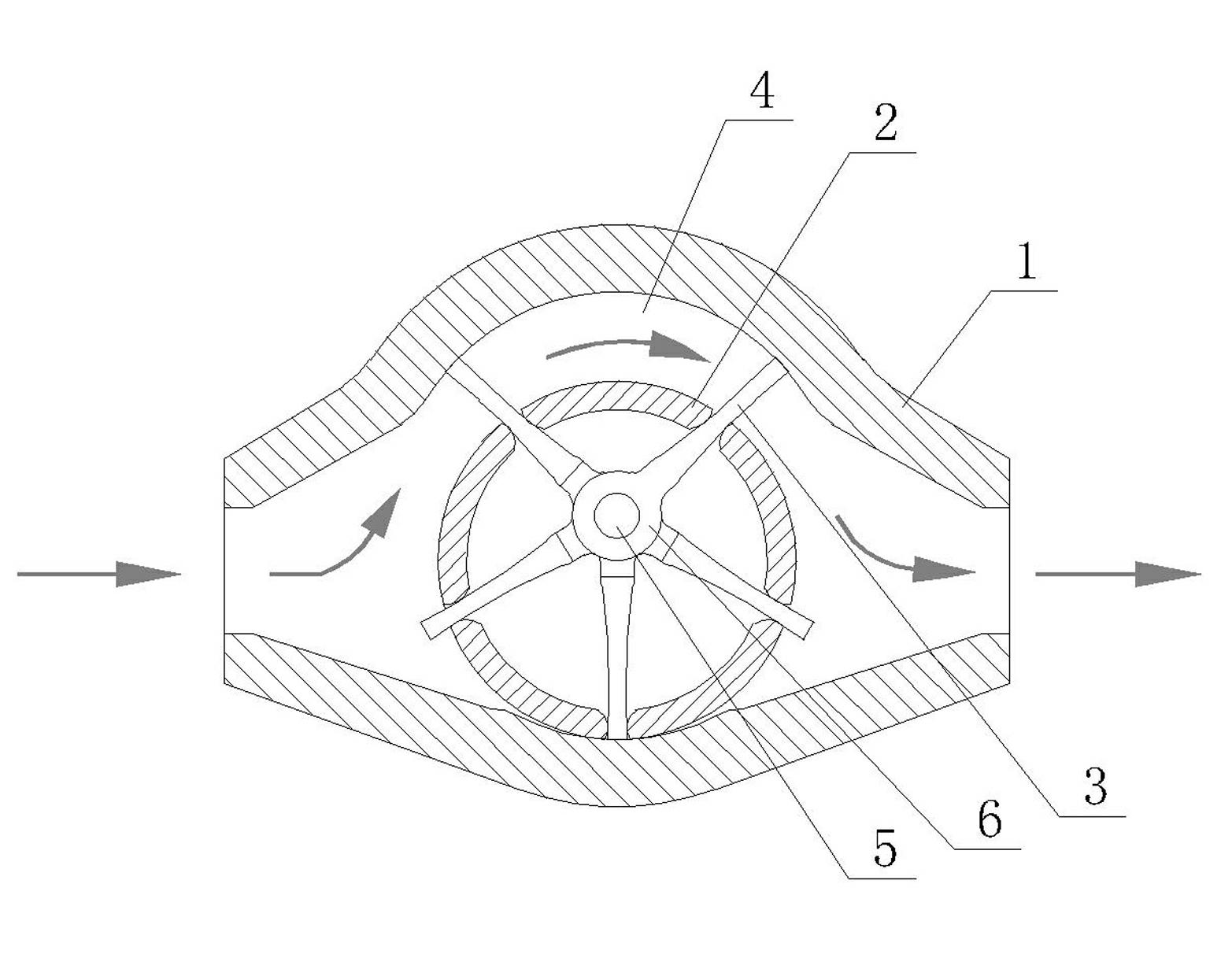
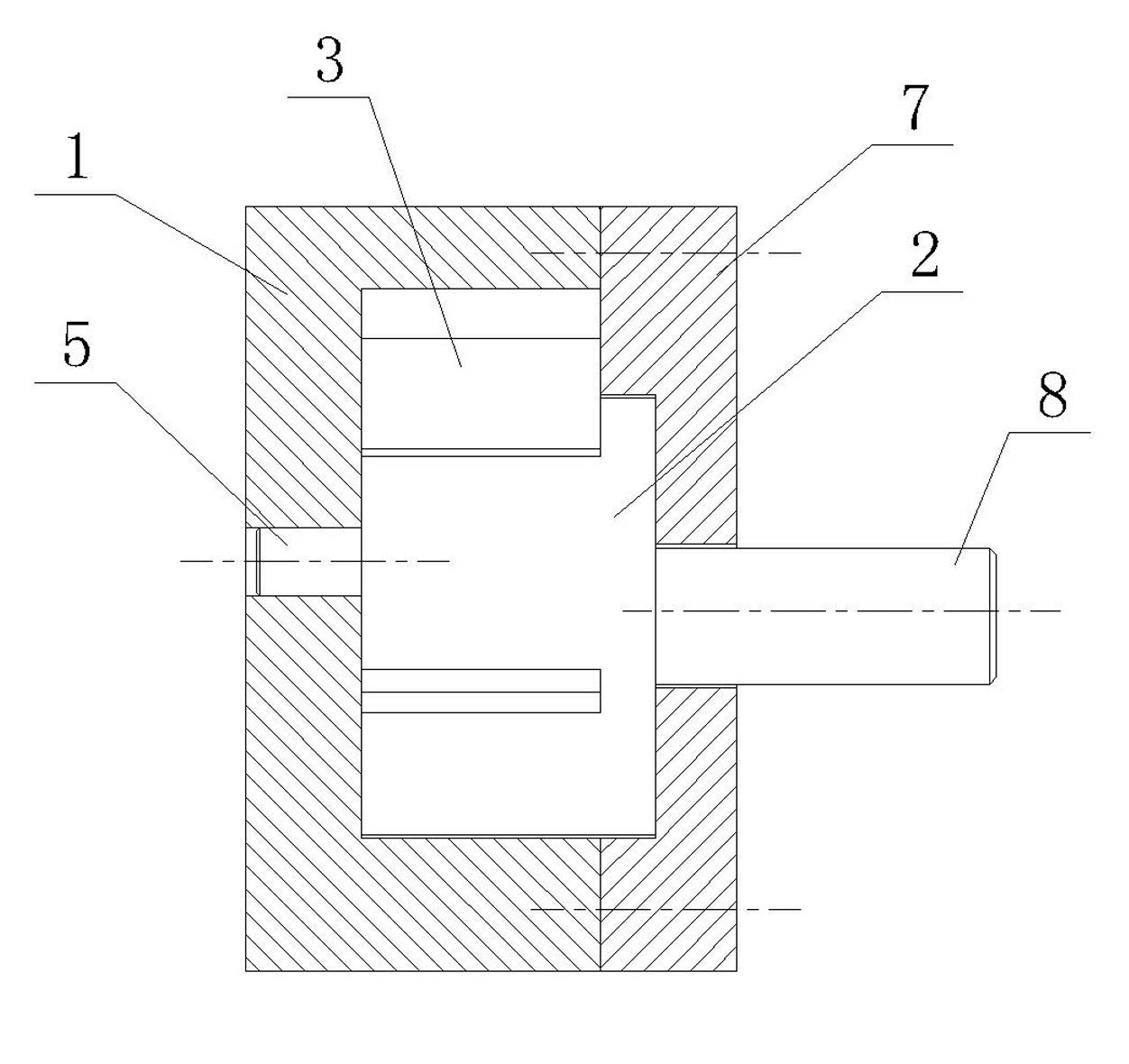
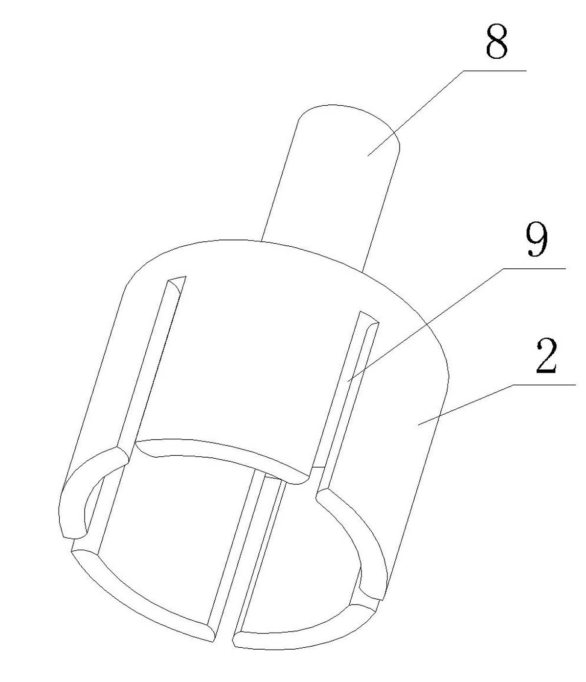
[0018] The accompanying drawings show the technical solution of the present invention and its embodiments, and the relevant details and working principles of the embodiments will be further described below in conjunction with the accompanying drawings.

[0019] Refer to attached figure 1 , 2 , 3, 4, this kind of vane pump, including stator 1, rotor 2, vane 3 (the vane is five pieces), vane shaft 5 and end cover 7, stator 1 has the inner surface of cylindrical hole 4, end cover 7 is passed through the screw It is fixedly connected with the stator 1, and the rotor 2 is a cylinder with a radial groove 9. One end of the rotor 2 is open and has a hollow structure. The other end of the rotor 2 is connected to the prime mover. Installed in the cylindrical hole 4 of the stator, the blade 3 slides freely in the radial groove 9 of the rotor, the blade shaft 5 is installed coaxially with the cylindrical hole 4 of the stator, and the blade shaft 5 is fixed on the side cover of the stator...


PUM


Abstract

The invention discloses a blade pump comprising a stator, a rotor and blades. The stator has an inner surface of a cylindrical hole, the rotor is a cylinder with a radial slot, the rotor is eccentrically mounted in the cylindrical hole of the stator, the blades freely slide in the radial slot of the rotor, wherein the blade pump comprises a blade shaft, and the blade shaft and the cylindrical hole of the stator are coaxially mounted; the blades are connected to the blade shaft, every blade forms an impeller with fixed external diameter, the impeller is rotatably cooperated with the inner surface of the cylindrical hole of the stator. The blade pump has the advantages of simple structure, convenience in manufacturing, small energy consumption, steady performance and long service life, more important, the blade pump can be applied to the transportation of gas, liquid such as water, and the like.

Description

technical field [0001] The invention relates to a vane pump. Background technique [0002] The vane pump is mainly composed of a rotor, a stator (that is, the pump body), blades and end covers. The stator has an inner surface with a cylindrical hole, and the rotor is a cylinder with radial grooves. The blades are placed in the grooves, and the blades can move freely in the grooves. Sliding, the rotor is mounted eccentrically in the cylindrical bore of the stator. The vane pump in the prior art generally refers to the vane pump, and its vanes are of vane type. When the rotor is driven by the prime mover to rotate, the vanes are tightly pressed in the stator by centrifugal force or spring force or pressure oil from the root of the vane. On the surface, in the first half of the rotation of the rotor, the space surrounded by two adjacent blades gradually increases to form a partial vacuum to suck the liquid, and in the second half of the rotation, the space gradually decreases...

Claims


Application Information

Patent Timeline
Patent Type & Authority Applications(China)
IPC IPC(8): F04C2/344
Inventor 肖义堃
Owner 肖义堃
Why Eureka
Try Eureka