
Radial rolling bearing seat assembly structure with good vibration absorption

A rolling bearing and assembly structure technology, applied in the field of machinery, can solve the problems of loud noise, poor vibration damping ability, and low bearing life, and achieve the effect of convenient assembly and low cost

Inactive Publication Date: 2011-11-23
张华林
View PDF4 Cites 5 Cited by
  • Summary
  • Abstract
  • Description
  • Claims
  • Application Information

AI Technical Summary

Problems solved by technology

Rolling bearings are easy to use and maintain, reliable in operation, and good in starting performance; their disadvantage is that the radial rolling bearing seat of the prior art has poor vibration damping ability. The additional vibration force of the dynamic unbalance generated by the rotor's own rotation is also subjected to the instantaneous impact force generated by the irregular random vibration during the driving process of the vehicle, especially the impact force of the instantaneous high-frequency vibration, resulting in the contact pressure between the rolling body of the bearing and the inner and outer rings. The stress is multiplied, and the damage to the bearing is great, resulting in a loud noise when the shaft rotates at high speed, and the bearing life is low, so the structure of the bearing seat needs to be improved

Method used


Image

  • Radial rolling bearing seat assembly structure with good vibration absorption
  • Radial rolling bearing seat assembly structure with good vibration absorption

Examples


Embodiment Construction

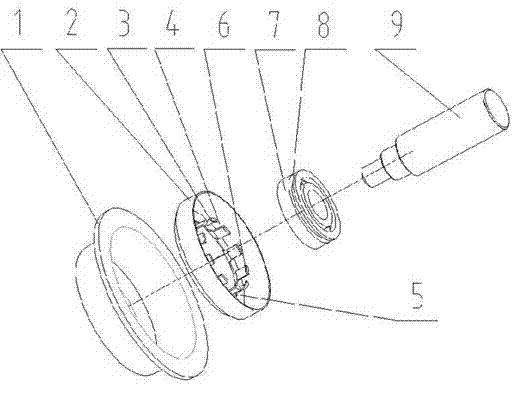
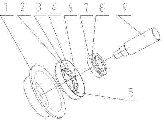
[0022] See attached figure 1 , a radial rolling bearing assembly structure shown in the embodiment of the present invention is composed of a bearing housing 1, a damping ring, a radial rolling bearing, and a shaft 9, and the radial rolling bearing is composed of an inner ring, an outer ring 7, rolling elements and a cage Composed of four parts, the outer ring 7 of the damping ring of the radial rolling bearing is provided with an axial stop groove 8 . The inner ring of the radial rolling bearing cooperates with the shaft 9 and rotates together with the shaft 9 . The damping ring is composed of the outside 2 of the damping ring, the bottom 5 of the damping ring, and the petals 3 inside the damping ring to form an integrated structure. In this embodiment, there are 10 petals inside the damping ring. The vibration damping ring is a metal part, which is installed between the bearing seat 1 and the outer ring 7 of the radial rolling bearing, and its outer side 2 and bottom 5 ar...


PUM


Abstract

The invention relates to a radial rolling bearing seat assembly structure with good vibration absorption. The structure comprises a bearing seat and a radial rolling bearing, wherein the radial rolling bearing consists of an inner ring, an outer ring, a rolling body and a retainer and is provided with an axial stop groove; the inner ring is matched with a shaft and rotates together with the shaft; the structure also comprises a metallic vibration absorption ring, wherein the vibration absorption ring is arranged between the bearing seat and the outer ring of the radial rolling bearing, the outer side and the bottom of the vibration absorption ring consist of a U-shaped outer edge and a bottom edge in a mode of rotating by using the central line of the shaft as a rotating center, and the inner side of the vibration absorption ring consists of a U-shaped inner edge in a mode of continuously rotating around the rotating center in equal clearance, so that the petal-like and roughly rotary vibration absorption ring, the inner side of which is provided with an equal central angle gap, is formed; the outer side of the vibration absorption ring is matched with and fastened to the bearing seat; and the protrusion on the petal-like body of the vibration absorption ring is embedded and limited in the axial stop groove of the radial rolling bearing. The structure has the advantages of good vibration absorption, low working noise and long service life of the bearing.

Description

technical field [0001] The invention relates to the technical field of machinery, in particular to an assembly structure of a radial rolling bearing seat with good damping performance. Background technique [0002] In the prior art, radial rolling bearings are generally composed of four parts: inner ring, outer ring, rolling element and cage. In most cases, the inner ring matches the shaft and rotates together with the shaft; It plays a supporting role; the rolling elements are evenly distributed between the inner ring and the outer ring by means of the cage, and the cage can make the rolling elements evenly distributed, prevent the rolling elements from falling off, and guide the rolling elements to rotate for lubrication. Rolling bearings are easy to use and maintain, reliable in operation, and good in starting performance; the disadvantage is that the radial rolling bearing seat of the prior art has poor vibration damping ability. The additional vibration force of the dy...

Claims


Application Information

Patent Timeline
IPC IPC(8): F16C27/00F16C33/58F16F15/121
Inventor 张华林
Owner 张华林
Learn More