Speed reducer lubricating device for oilfield pumping unit

A technology of lubricating device and pumping unit, applied in transmission parts, gear lubrication/cooling, mechanical equipment, etc., can solve the problem that lubricating oil is scarce, cannot meet the lubrication of driven shaft bearings, and the oil scraper cannot normally scrape lubrication oil and other issues

Active Publication Date: 2011-11-23
XUZHOU DONGFANG TRANSMISSION MACHINERY
View PDF4 Cites 11 Cited by
  • Summary
  • Abstract
  • Description
  • Claims
  • Application Information

AI Technical Summary

Problems solved by technology

[0003] However, most of the oil wells in the oil field are heavy oil wells. According to the rated speed of the reducer for the pumping unit, it can no longer meet the needs of the oil field. Most of the pumping units operating in the oil field now work between 1 to 3 revolutions per minute. When the speed of th

Method used


Image

  • Speed reducer lubricating device for oilfield pumping unit
  • Speed reducer lubricating device for oilfield pumping unit
  • Speed reducer lubricating device for oilfield pumping unit

Examples


Embodiment Construction

[0025] The present invention will be further described below in conjunction with accompanying drawing.

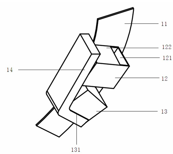
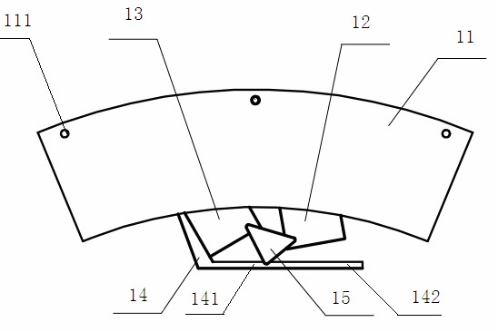
[0026] Such as figure 1 , figure 2 and Figure 6 As shown, a lubricating device for a reducer for an oil field pumping unit includes an oil lifter 1 and an oil storage pan 2; the oil lifter 1 is mainly composed of a support plate 11, a first oil box 12, a second oil box 13, an oil guide The support plate 14 is composed of several support plate mounting holes 111.

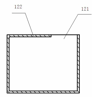
[0027] Such as figure 1 , image 3 and Figure 4 As shown, the first oil box 12 and the second oil box 13 are respectively provided with a first oil lifting port 121 and a second oil lifting port 131 on the outer side, wherein the first oil lifting port 121 is provided with a baffle plate 122 to To prevent the lubricating oil from being lost prematurely, it cannot flow into the oil storage pan 2 sufficiently, and the second oil box 13 is protected by the oil guide plate 14, so it is not necessary to inst...


PUM


Abstract

The invention discloses a speed reducer lubricating device for an oilfield pumping unit, and belongs to the field of speed reducer lubrication. The speed reducer lubricating device comprises an oil lifter and an oil storage tray; the oil lifter is arranged on a driven gear; and the oil storage tray is fixed on a box seat and positioned beside an oil wiper in the cavity of a box body. The speed reducer lubricating device has the advantages that lubrication of bearings of a driven shaft and an intermediate shaft is ensured under the condition of meeting low stroke frequency of a speed reducer for the oilfield pumping unit; and the oil lifter is provided with two oil boxes which are opened in two directions respectively, so that the oil lifter can lift the lubricating oil no matter the rotating direction of the speed reducer is clockwise or anticlockwise.

Description

technical field [0001] The invention relates to a lubricating device for a reducer, in particular to a lubricating device for a reducer used in an oil field pumping unit, and belongs to the field of lubricating the reducer. Background technique [0002] At present, the commonly used pumping unit reducers generally use two-stage transmission split-flow double-arc gear reducers. The intermediate shaft and driven gear are a pair of gears that mesh with each other at low speeds, and the intermediate shaft is a shaft-toothed herringbone gear. , the driven gear is a herringbone gear that is interference fit on the driven shaft. Commonly used pumping unit reducers generally use oil immersion lubrication, which is to inject lubricating oil into the box, immerse the driven gear and the left and right spiral gears to a certain height, and use the rotational motion of the gears to provide the required oil for the bearings of the reducer. lubricating oil. Such as Figure 7 As shown, t...

Claims


Application Information

Patent Timeline
IPC IPC(8): F16H57/04
CPCF16H57/0495F16H57/0427F16H57/04
Inventor 高徐生沈晓侠李寒杰吴庆超
Owner XUZHOU DONGFANG TRANSMISSION MACHINERY
Why Eureka
Try Eureka