Composite diaphragm of pulp pump and process for producing composite diaphragm

A composite diaphragm and pulp pump technology, applied in the direction of diaphragms, mechanical equipment, etc., can solve problems such as difficulty in ensuring reliability and service life

Inactive Publication Date: 2011-11-23
上海麦特密封件有限公司
View PDF9 Cites 1 Cited by
  • Summary
  • Abstract
  • Description
  • Claims
  • Application Information

AI Technical Summary

Problems solved by technology

At present, the diaphragms used in slurry pumps are all rubber diaphragms with a single structure. Once the diaphragm cracks, great stress will be generated at the crack, and the diaphragm will be torn quickly, which makes it difficult to ensure reliability and long service life. In addition , due to the different properties of the medium on both sides of the diaphragm, one side of the diaphragm of a general slurry pump is in contact with the alkaline slurry liquid, while the other side is in contact with the hydraulic oil, which requires the reliability and service life of the diaphragm to withstand the corrosion of two different media

Method used


Image

  • Composite diaphragm of pulp pump and process for producing composite diaphragm
  • Composite diaphragm of pulp pump and process for producing composite diaphragm
  • Composite diaphragm of pulp pump and process for producing composite diaphragm

Examples


Embodiment Construction

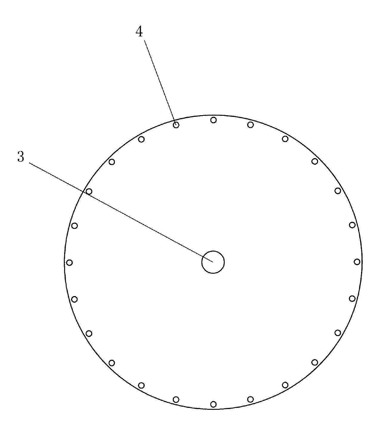
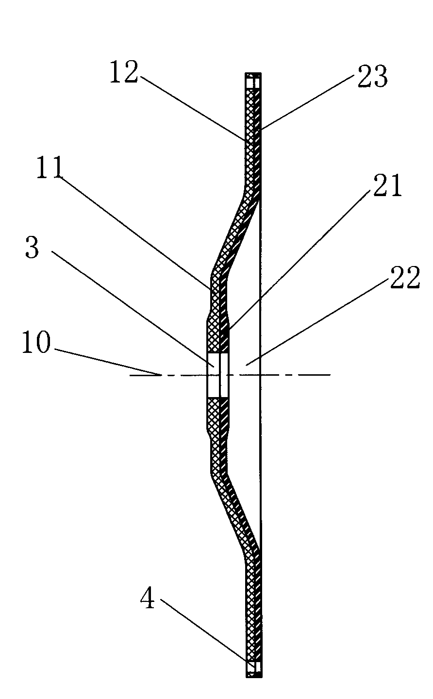
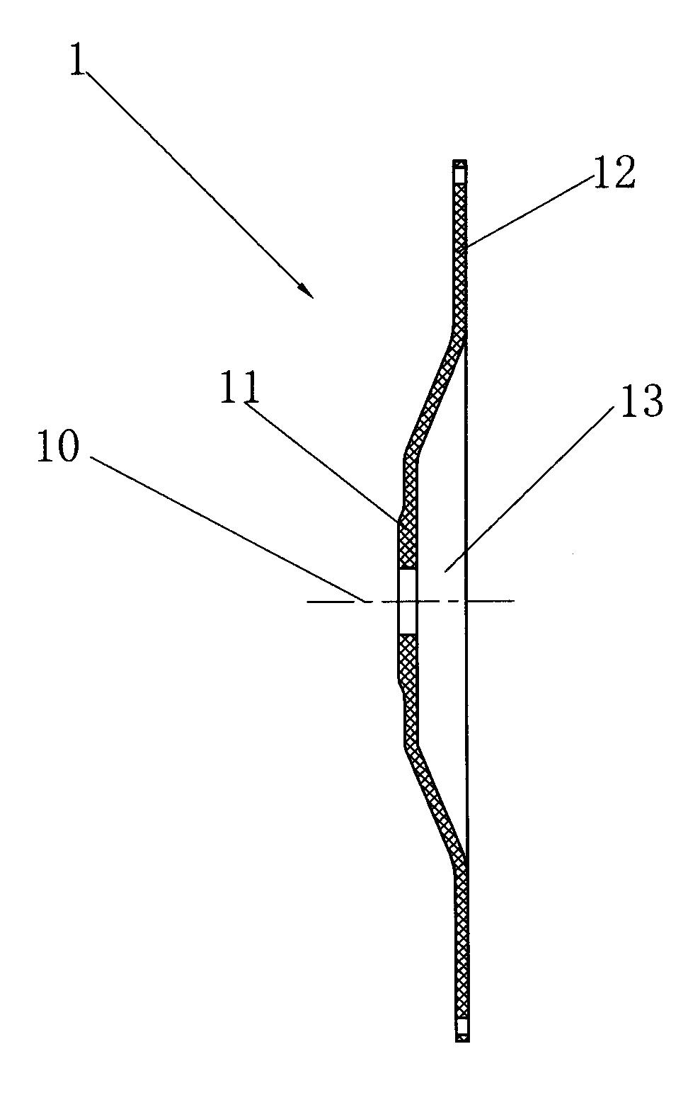
[0021] Such as Figure 1-4 As shown, the specific embodiment of the present invention is a composite diaphragm of a slurry pump, which includes a rubber layer 1 and a polyurethane layer 2. The rubber layer 1 has a circular structure and includes axial protrusions along the central axis 10 of the composite diaphragm. The raised part 11 with an isosceles trapezoidal structure in cross section and the flange 12 extending along the periphery of the raised part 11, wherein a corresponding recessed part 13 is formed on the other side of the raised part 11 relative to the rubber layer 1, so The polyurethane layer 2 is adapted to the shape and structure of the rubber layer 1, by Figure 4 It can be seen that the polyurethane layer has a first protruding portion 21 and a corresponding first concave portion 22 and a first flange 23 extending along the periphery of the first protruding portion 21, and the first protruding portion 21 of the polyurethane layer 2 Compatible with the recess...


PUM


Abstract

The invention relates to a composite diaphragm of a pulp pump and a process for producing the composite diaphragm. The composite diaphragm comprises a rubber layer and a polyurethane layer, wherein the rubber layer is in a circular shape and comprises a bulge part and a flange; the bulge part bulges along the axial direction of a central axis of the rubber layer; the cross section of the bulge part is in an isosceles trapezoid shape; the flange extends along the periphery of the bulge part; a corresponding recess part is formed on the other side of the bulge part of the rubber layer; the structure of the polyurethane layer is matched with the structure of the rubber layer; the bulge part of the polyurethane layer is matched with the recess part of the rubber layer to form adhesion and to be fixed; a through hole is formed in a central position of the composite diaphragm; and a plurality of positioning holes are distributed in an axial direction at an equal angle around the central axis on the flange of the composite diaphragm. The process comprises the following processes of material cutting, molding vulcanizing, adhesion vulcanizing, secondary vulcanizing, marking punching, edge trimming and checking. The composite diaphragm produced by the process has the advantages of high reliability, long service life and the like.

Description

technical field [0001] The invention specifically relates to a composite diaphragm of a slurry pump and a production process thereof. Background technique [0002] Due to the particularity of the working environment, diaphragm products for slurry pumps are required to achieve corresponding reliability and service life under the working conditions of high pressure, fatigue resistance, and resistance to different media. At present, the diaphragms used in slurry pumps are all rubber diaphragms with a single structure. Once the diaphragm cracks, great stress will be generated at the crack, and the diaphragm will be torn quickly, which makes it difficult to ensure reliability and long service life. In addition , due to the different properties of the medium on both sides of the diaphragm, one side of the diaphragm of a general slurry pump is in contact with the alkaline slurry liquid, while the other side is in contact with the hydraulic oil, which requires the reliability and se...

Claims


Application Information

Patent Timeline
Patent Type & Authority Applications(China)
IPC IPC(8): F16J3/02B32B25/08B29C35/02
Inventor 郑元然康联社肖飞
Owner 上海麦特密封件有限公司
Why Eureka
Try Eureka